Rotary encoder fixing device
A technology for rotary encoders and fixing devices, which is applied in the direction of transmitting sensing components, supporting machines, mechanical equipment, etc. by using optical devices, which can solve the problems of difficult installation of rotary encoders, improve the scope of application, ensure accuracy, and ensure The effect of stability
- Summary
- Abstract
- Description
- Claims
- Application Information
AI Technical Summary
Problems solved by technology
Method used
Image

Examples
Embodiment 1
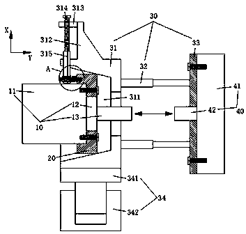
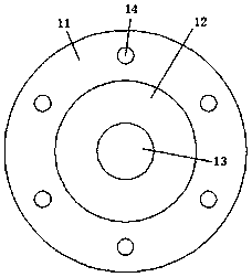
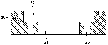
[0030] see Figure 1-Figure 6 As shown, the present invention provides the following technical solutions: a rotary encoder fixing device, including a rotary encoder 10, a mechanical device 40 and a fixing device main body, wherein the rotary encoder 10 includes an encoder host 11 and an encoder shaft 13, and the mechanical device 40 includes a mechanical host 41 and a mechanical shaft 42. The main body of the fixing device includes a coaxially connected matching component and a coaxial positioning component 30, and the two components are detachably connected, wherein the matching component and the encoder shaft 13 form a coaxial and the encoder shaft 13 passes through the matching assembly and extends into the interior of the coaxial positioning assembly 30. The coaxial positioning assembly 30 and the mechanical shaft 42 form a coaxial installation, and the mechanical shaft 42 extends into the coaxial The center locates the inside of the assembly 30 and forms a connection with...
Embodiment 2
[0044] see Figure 1-Figure 6 As shown, and based on the structure disclosed in the first embodiment above, in this embodiment, the coaxial center positioning assembly 30 further includes a telescopic rod 32 , and the telescopic rod 32 is fixed between the positioning sleeve 31 and the mounting plate 33 .
[0045] In this embodiment, the telescopic rod 32 is used to realize the connection between the positioning sleeve 31 and the mounting plate 33, so that the distance between the positioning sleeve 31 and the mounting plate 33 can be adjusted, thereby making the connection between the encoder shaft 13 and the mechanical shaft 42 more accurate. It is easy to handle and can be fitted with couplings of different sizes.
Embodiment 3
[0047] see Figure 1-Figure 6 As shown, and based on the structure disclosed in the first or second embodiment above, in this embodiment, the coaxial center positioning assembly 30 also includes a mounting base 34, and the mounting base 34 is fixed on the bottom of the positioning sleeve 31, and realizes that the positioning sleeve 31 directly fixed.
[0048] In this embodiment, preferably, the installation base 34 includes a bottom plate 341 and a lifting seat 342 , the bottom plate 341 is integrally formed on the bottom of the positioning sleeve 31 and fixed on the top of the lifting seat 342 .
[0049] In this embodiment, based on the additional installation base 34, the fixing of the positioning sleeve 31 itself is more stable, that is, there is a double fixation supported by the installation plate 33 and the installation base 34, so as to further avoid the jumping phenomenon of the positioning sleeve 31; and the installation base 34 can be formed based on the base plate ...
PUM
 Abstract
Description
Claims
Application Information
 - Generate Ideas
- Intellectual Property
- Life Sciences
- Materials
- Tech Scout
- Unparalleled Data Quality
- Higher Quality Content
- 60% Fewer Hallucinations
Browse by: Latest US Patents, China's latest patents, Technical Efficacy Thesaurus, Application Domain, Technology Topic, Popular Technical Reports.
© 2025 PatSnap. All rights reserved.Legal|Privacy policy|Modern Slavery Act Transparency Statement|Sitemap|About US| Contact US: help@patsnap.com