Fire hose connector

A technology for fire hoses and connectors, which is applied in the direction of hose connection devices, pipes/pipe joints/fittings, mechanical equipment, etc., and can solve the problem of uneven circumferential force on the parts connected by fire hoses and the impact of fire hoses on fire protection Rescue effectiveness, joint leakage and other issues, to avoid leakage or even breakage, improve stability, and increase frictional resistance

Pending Publication Date: 2020-02-04
应急管理部四川消防研究所
View PDF0 Cites 0 Cited by
  • Summary
  • Abstract
  • Description
  • Claims
  • Application Information

AI Technical Summary

Problems solved by technology

The performance of the fire hose directly affects the effectiveness of fire rescue. Therefore, it is necessary to test the performance of the fire hose when it leaves the factory. When it leaves the factory, the fire hose is equipped with metal joints. When testing the pressure bearing capacity of the fire hose, it is necessary to fix one end of the fire hose to the fire hose, and the other end must be sealed and blocked to test the pressure bearing capacity. Therefore, it is necessary to design the corresponding fire hose With connection joints, and the existing connection joints generally use two compression tubes with flanges, one compression tube is sleeved on the outside of the fire hose, the other compression tube is inserted into the inside of the fire hose, and The fire hose is tightly connected between the two compression pipes by means of bolt connection, and when the connection is adopted in this way, when the bolts compress the two compression pipes, the bolts in all directions are connected When tightening at the same time, it is impossible to ensure that the stress conditions between the two compression tubes are the same everywhere, which will cause the circumferential force of the fire hose connection part of the compression tube during the compression of the fire hose. Unequal, when carrying out the pressure bearing test, it is easy to cause leakage or even breakage at the connection, and cannot well complete the test requirements for the pressure bearing capacity of the fire hose

Method used


Image

  • Fire hose connector
  • Fire hose connector

Examples


Embodiment Construction

[0020] The present invention will be further described below with reference to the accompanying drawings and embodiments, and the mode of the present invention includes but not limited to the following embodiments.

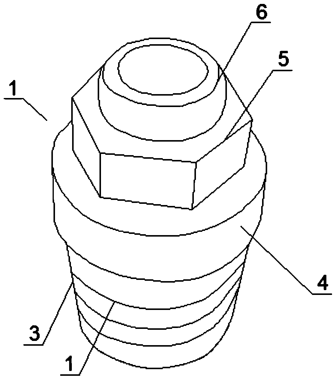
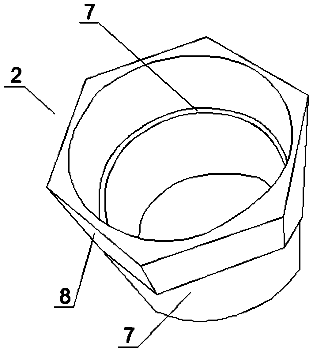
[0021] Such as Figure 1~2 Shown:

[0022] A connector for a fire hose, consisting of an inner connector 1 and an outer connector 2, the outer connector is screwed to the inner connector; specifically, the inner connector 1 includes an inner plug inserted into the fire hose 3. The inner plug 3 is a hollow tubular structure. After the inner plug 3 is inserted into the fire hose, the inner wall of the fire hose is tightly attached to the outer wall of the inner plug, and the pressure of the liquid in the fire hose is realized through the inner plug. Transfer, in order to increase the tight friction between the outer wall of the inner plug and the inner wall of the fire hose, a plurality of printing grooves distributed at intervals can be set on the outer wall of th...


PUM


Abstract

The invention discloses a fire hose connector. The fire hose connector comprises an inner connecting piece and an outer connecting piece sleeving the inner connecting piece; the inner connecting piececomprises an inner plug inserted into a fire hose, a fixing table connected with the inner plug, a dismounting table connected with the fixing table, and an outer connector connected with the fixingtable; the outer connecting piece comprises a pressing part which sleeves the outer side of the fire hose and is matched with the inner plug, and a locking table which is connected with the pressing part and matched with the fixing table; and the fixing table and the locking table are matched, connected and locked in a threaded connection manner. The pressing part sleeves the outer side of the fire hose, and the inner plug is inserted into the inner side of the fire hose and is screwed through screw threads between the locking table and the fastening table, so that the connection of the fire hose is realized, uniform stress is realized when the fire hose is connected, leakage or even breakage of the fire hose at the connection location due to the uneven stress is avoided, and the guaranteeis improved for smooth testing of the fire hose.

Description

technical field [0001] The invention relates to the technical field of fire fighting equipment, in particular to a fire hose connector. Background technique [0002] The fire hose is a hose used to transport high-pressure water or foam and other flame-retardant liquids. The fire hose is lined with rubber, and the outer surface is wrapped with linen braid, or made of polymer materials such as polyurethane. The two ends of the fire hose Both have metal connectors that can be attached to another hose to extend the distance or to a nozzle to increase the liquid spray pressure. The performance of the fire hose directly affects the effectiveness of fire rescue. Therefore, it is necessary to test the performance of the fire hose when it leaves the factory. When it leaves the factory, the fire hose is equipped with metal joints. When testing the pressure bearing capacity of the fire hose, it is necessary to fix one end of the fire hose to the fire hose, and the other end must be se...

Claims


Application Information

Patent Timeline
Patent Type & Authority Applications(China)
IPC IPC(8): F16L33/025F16L33/02
CPCF16L33/02F16L33/025
Inventor 李明轩
Owner 应急管理部四川消防研究所
Why Eureka
Try Eureka