
Anti-seismic structure for civil engineering

A seismic structure and civil engineering technology, applied in the direction of uniaxial trolleys, trolley accessories, trolleys, etc., can solve the problem that the shock-absorbing spring is prone to resonance, cannot adapt to complex terrain, and affects normal use, and achieves affordable prices and novel designs. , the effect of long service life

Active Publication Date: 2020-02-04
HENAN UNIVERSITY OF TECHNOLOGY
View PDF6 Cites 0 Cited by
  • Summary
  • Abstract
  • Description
  • Claims
  • Application Information

AI Technical Summary

Problems solved by technology

With the development of society, engineering structures are becoming larger and more complex. Super high-rise buildings, super-large bridges, giant dams, and complex subway systems are constantly emerging to meet people's living needs and also evolve into a symbol of social strength. , the fundamental problem that civil engineering needs to solve is the safety of the project, so that the structure can resist various natural or man-made forces. In the construction site of civil engineering, it is often necessary to use some trolleys that are convenient for transporting materials, but the existing trolleys cannot adapt Complicated terrain in civil engineering, poor shockproof effect
[0003] After searching, the Chinese patent discloses a civil engineering anti-seismic structure (authorized announcement number CN207045374U). This patent technology realizes the shock absorption of the trolley through the shock-absorbing spring, but the shock-absorbing spring is prone to resonance, and it is easy to cause self-shock under long-term compression. Weakened performance seriously affects normal use

Method used


Image

  • Anti-seismic structure for civil engineering
  • Anti-seismic structure for civil engineering
  • Anti-seismic structure for civil engineering

Examples


Embodiment Construction

[0021] The following will clearly and completely describe the technical solutions in the embodiments of the present invention with reference to the accompanying drawings in the embodiments of the present invention. Obviously, the described embodiments are only some, not all, embodiments of the present invention. Based on the embodiments of the present invention, all other embodiments obtained by persons of ordinary skill in the art without making creative efforts belong to the protection scope of the present invention.

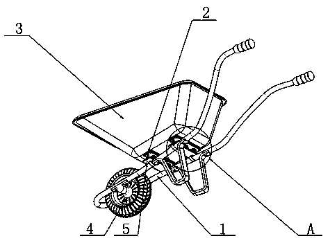
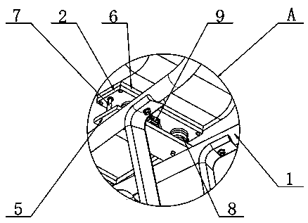
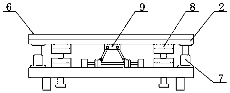
[0022] see Figure 1~5 , in an embodiment of the present invention, a civil engineering anti-seismic structure includes a chassis frame 1, a moving wheel 4 is rotatably connected to the inner side of one end of the chassis frame 1, and two lower fixing plates 5 arranged in parallel are fixed on the upper surface of the chassis frame 1 , the top of the chassis frame 1 is provided with a car bucket 3, and the positions below the car bucket 3 corresponding to the...


PUM


Abstract

The invention relates to the technical field of civil engineering, in particular to an anti-seismic structure for civil engineering. A seism-absorbing pad is attached between an upper fixed plate anda car hopper, air pressure supporting rods are fixed to two end part positions between the upper fixed plate and a lower fixed plate, and two symmetrically distributed buffer structures A are fixed toone sides of the air pressure supporting rods between the upper fixed plate and the lower fixed plate. The anti-seismic structure for civil engineering is novel in design and simple in principle. Byadopting two magnets for suspended seismic prevention, jolt and vibration generated by a civil engineering trolley during travelling will be reduced and counteracted gradually, so that an anti-seismiceffect is exerted and the problem that a carried object falls off as the trolley in the travelling process is affected by a pavement is avoided. The anti-seismic mode replaces a conventional anti-seismic mode by a spring, so that the anti-seismic structure for civil engineering is better in anti-seismic effect, long in service life and close to the people in price, and solves the problem that thewhole anti-seismic effect is affected as the performance of the spring is easily weakened while being oppressed for a long time.

Description

technical field [0001] The invention relates to the technical field of civil engineering, in particular to an anti-seismic structure of civil engineering. Background technique [0002] The purpose of civil engineering is to form the well-functioning, comfortable and beautiful spaces and passages required by human production or life. It is both a material need and a symbolic spiritual need. With the development of society, engineering structures are becoming more and more large and complex. Super high-rise buildings, super-large bridges, giant dams, and complex subway systems are constantly emerging to meet people's living needs and also evolve into a symbol of social strength. , the fundamental problem that civil engineering needs to solve is the safety of the project, so that the structure can resist various natural or artificial forces. In the construction site of civil engineering, it is often necessary to use some trolleys that are convenient for transporting materials,...

Claims


Application Information

Patent Timeline
Patent Type & Authority Applications(China)
IPC IPC(8): B62B1/24B62B5/00
CPCB62B1/24B62B5/0006B62B2202/00
Inventor 陈科委丁永刚闫静茹王浩然韩景芳
Owner HENAN UNIVERSITY OF TECHNOLOGY
Learn More