
Transmission mechanism and scanning table

A transmission mechanism and secondary transmission technology, applied in the field of medical equipment, can solve the problems of multi-height space, occupation, and height, and achieve the effect of less height space, increased travel range, and reduced height

Active Publication Date: 2021-10-15
SHANGHAI NEUSOFT MEDICAL TECH LTD +1
View PDF12 Cites 1 Cited by
  • Summary
  • Abstract
  • Description
  • Claims
  • Application Information

AI Technical Summary

Problems solved by technology

In this method, the height of the transmission mechanism of the scanning bed is at least equal to the sum of the height of the first-level transmission mechanism and the height of the second-level transmission mechanism. Therefore, the height is higher and more height space will be occupied.

Method used


Image

  • Transmission mechanism and scanning table
  • Transmission mechanism and scanning table
  • Transmission mechanism and scanning table

Examples


Embodiment approach

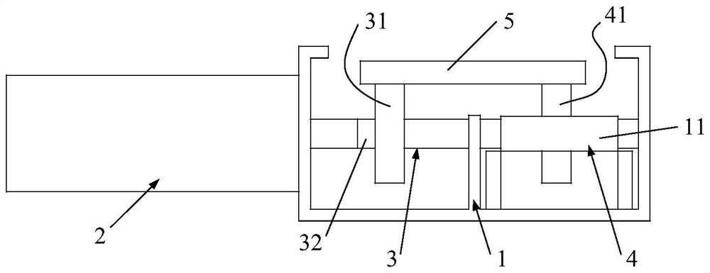
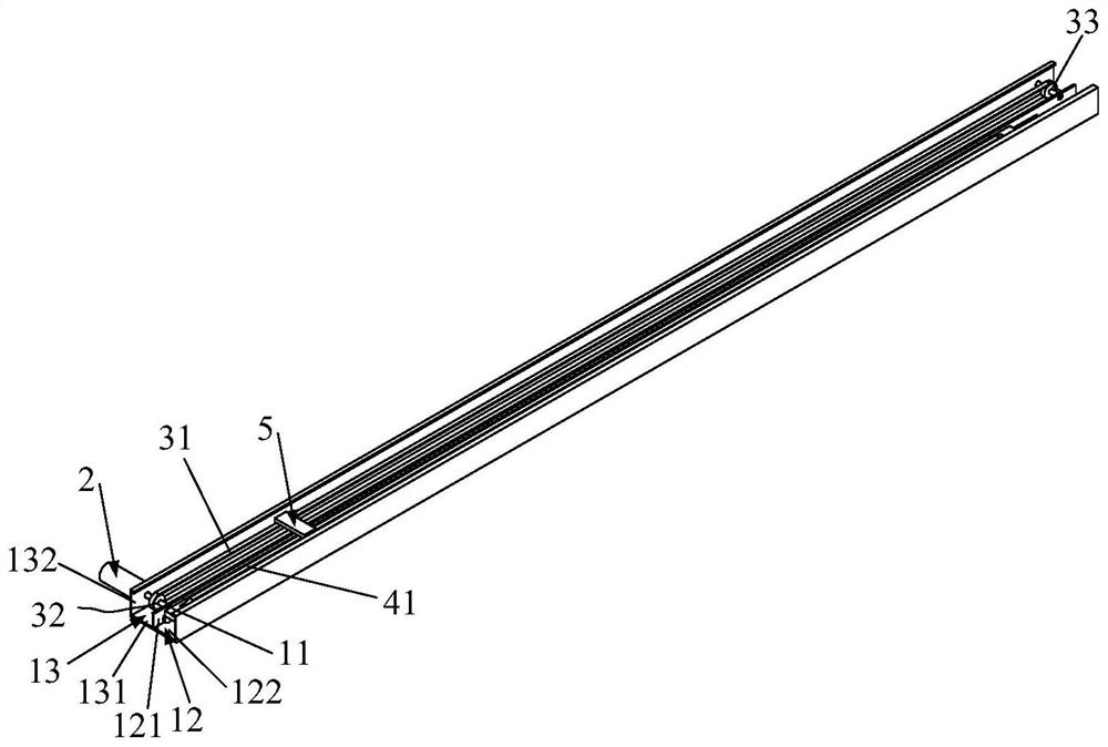
[0031] see Figure 1 to Figure 4, in the present application, one purpose of the primary transmission mechanism 3 is to drive so that the secondary transmission mechanism 4 moves, therefore, the primary synchronous belt 31 will rotate at the installation position, and one purpose of the secondary transmission mechanism 4 is to drive The driven object connected to the secondary transmission mechanism 4 (for example, the bed plate of the scanning bed or the moving parts of the machine tool, etc.) moves linearly. Therefore, based on the above two considerations at least, the primary transmission mechanism 3 and the secondary transmission mechanism are realized. 4 The structures arranged side by side may include a guide structure and a mounting structure connected to the guide structure, the guide structure is used to install the secondary transmission mechanism 4 to drive the driven object (for example, parts of a scanning bed or machine tool, etc.) to move linearly , and the ins...


PUM


Abstract

The application discloses a transmission mechanism and a scanning bed. The transmission mechanism includes a bracket, a motor mounted on the bracket, a primary transmission mechanism, and a secondary transmission mechanism, wherein the motor is connected to the primary transmission mechanism, and the primary transmission mechanism includes a primary timing belt; The secondary transmission mechanism is arranged side by side with the primary transmission mechanism, and includes a secondary synchronous belt connected with the primary synchronous belt. Since the primary transmission mechanism and the secondary transmission mechanism are arranged side by side, the overall height of the transmission mechanism is equal to the highest of the primary transmission mechanism and the secondary transmission mechanism, and the method of superimposing the primary transmission mechanism and the secondary transmission mechanism In comparison, the height of the transmission mechanism is reduced, and it occupies less height space, which is convenient for other structural designs. In addition, the primary transmission mechanism and the secondary transmission mechanism adopt synchronous belts to increase the stroke range.

Description

technical field [0001] The application relates to the field of medical equipment, in particular to a transmission mechanism and a scanning bed. Background technique [0002] The existing scanning bed includes a transmission mechanism and a bed board. The transmission mechanism includes a primary transmission mechanism and a secondary transmission mechanism. The primary transmission mechanism and the secondary transmission mechanism are superimposed and arranged up and down. In this way, the height of the transmission mechanism of the scanning bed is at least equal to the sum of the height of the primary transmission mechanism and the height of the secondary transmission mechanism. Therefore, the height is higher and more height space will be occupied. This technology can refer to the Chinese patent application whose publication number is CN107137084A and the name is scanning system. Contents of the invention [0003] In order to overcome some or all of the problems in t...

Claims


Application Information

Patent Timeline
Patent Type & Authority Patents(China)
IPC IPC(8): A61G13/10A61G13/00
CPCA61G13/00A61G13/10A61G2210/00
Inventor 钱悦王益宁徐志坚王轶楠
Owner SHANGHAI NEUSOFT MEDICAL TECH LTD
Learn More