Universal eye-catching float
A general-purpose and eye-catching technology, which is applied in the field of fish floats, can solve the problems of small expression range of eye-catching floats, difficulty in achieving rich shape changes in visible surface contours, and unfounded problems
- Summary
- Abstract
- Description
- Claims
- Application Information
AI Technical Summary
Problems solved by technology
Method used
Image
Examples
Embodiment 1
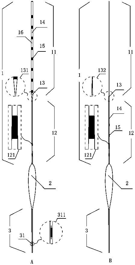
[0058] The fish float of present embodiment is as figure 1 As shown, the general-purpose eye-catching fish float includes a float tail 1, a float body 2 and a float foot 3. The float tail 1 includes a flat float section 11 and a thin tail 12. The float tail 1 is covered with a float eye coating 14 and a scale line coating 15. . The flat floating section 11 is set downward from the top of the floating tail. At this time, the fourth mesh 16 on the flat floating section 11 is the fourth mesh of the floating tail 1. The drift section with a width greater than 1.1mm in the flat drift section 11 is an eye-catching drift section, such as figure 1 As shown in A, in the present embodiment, the eye-catching drift section is slightly smaller than the length of the flat-shaped drift section 11, and its lowermost end is about 94mm away from the upper end point. The two front and rear surfaces corresponding to the eye-catching floating section with a width greater than 1.1mm that can play...
Embodiment 2
[0061] In addition to Example 1 such as figure 1 The front and rear contours of the flat drift section 11 shown in B are designed with a flat tail and belong to a film shape. The difference between this embodiment and embodiment 1 is that the front and rear contours of the flat drift section 11 can also be designed to prevent head-heavy, etc. to understand the film-like contour shape. Specifically: the length of the flat floating section 11 is still 100mm, the left and right contours of the visible surface are still parallel strips, the front and rear contours of the flat floating section 11 are designed to prevent head-heaviness with a thickness gradually increasing from top to bottom, and the thickness of the top end The thickness of the bottom end is 0.2mm, and the thickness of the bottom end is 0.6mm, and then it is connected with the top end of the thin tail 12. The last 10mm near the lower end of the flat floating section 11 is still the transition part 13, and the transi...
Embodiment 3
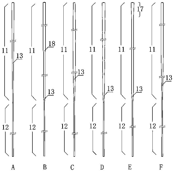
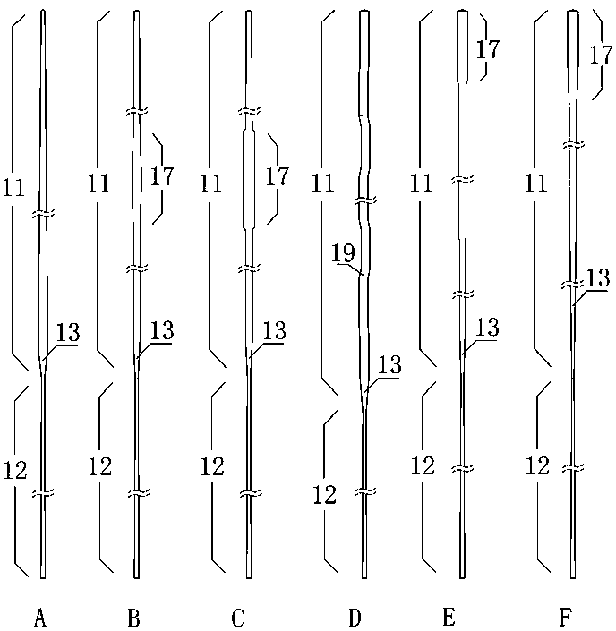
[0064] This example figure 2 image 3 A variety of eye-catching floating section left and right contour shapes are listed to understand the concept of strips, left and right contour shapes, and the position of transition parts. figure 2 image 3 It is a schematic diagram, and usually the actual product appears longer and thinner, which is more in line with the concept of a long strip. For example, the partially widened floating section 17 obviously does not belong to the wing, such as image 3 B Partial widening of the left and right contour lines from straight lines to arc-shaped lines still belongs to the category of gradual widening and is also a simple replacement method in terms of shape.
PUM
 Abstract
Description
Claims
Application Information
 - R&D
- Intellectual Property
- Life Sciences
- Materials
- Tech Scout
- Unparalleled Data Quality
- Higher Quality Content
- 60% Fewer Hallucinations
Browse by: Latest US Patents, China's latest patents, Technical Efficacy Thesaurus, Application Domain, Technology Topic, Popular Technical Reports.
© 2025 PatSnap. All rights reserved.Legal|Privacy policy|Modern Slavery Act Transparency Statement|Sitemap|About US| Contact US: help@patsnap.com


