
Bounds checking

A lower limit and upper limit technology, applied in the field of limit checking, can solve problems such as time-consuming, increased power consumption, and increased circuit size

Active Publication Date: 2020-01-31
ARM LTD
View PDF5 Cites 0 Cited by
  • Summary
  • Abstract
  • Description
  • Claims
  • Application Information

AI Technical Summary

Problems solved by technology

This in turn increases circuit size and thus power consumption
Also, comparing such a large number of bits becomes time-consuming

Method used


Image

  • Bounds checking
  • Bounds checking
  • Bounds checking

Examples


Embodiment Construction

[0015] Before discussing the embodiments with reference to the figures, the following description of the embodiments is provided.

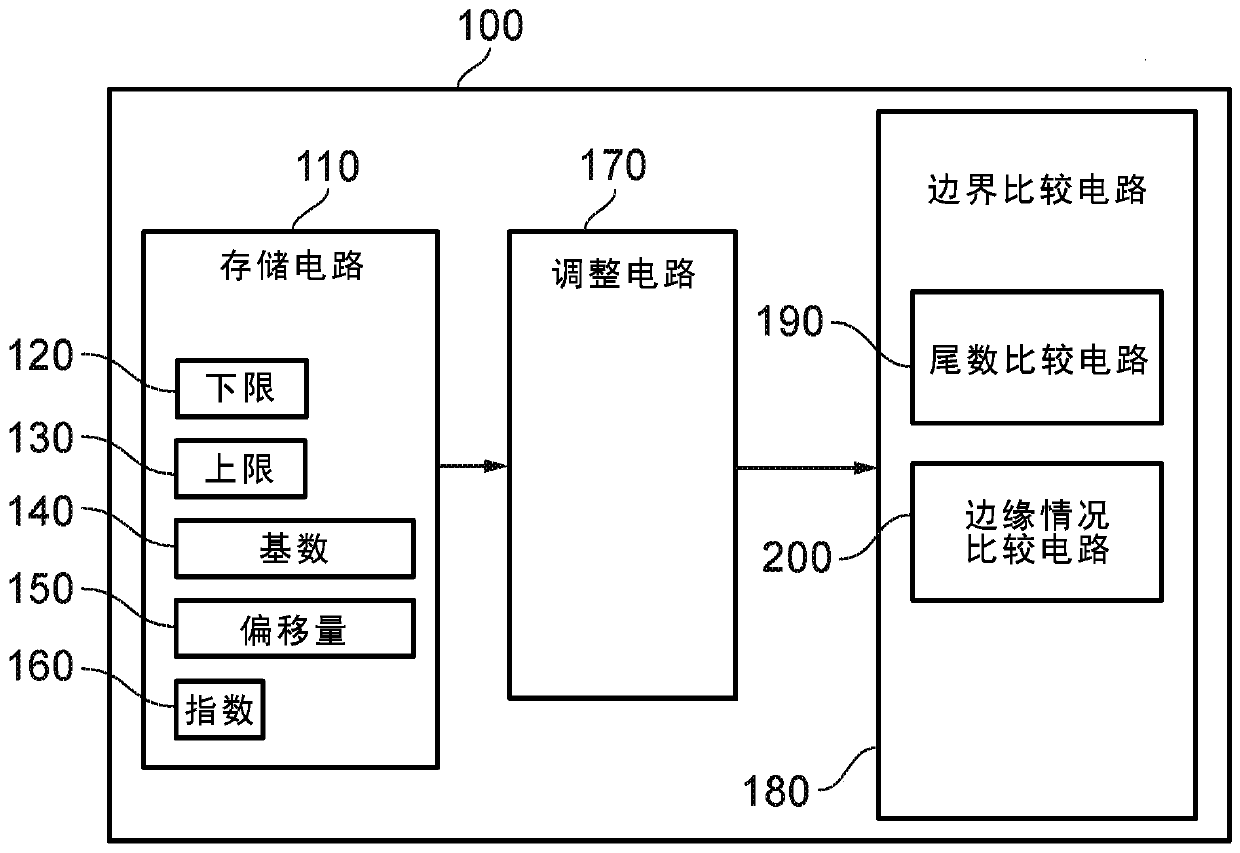
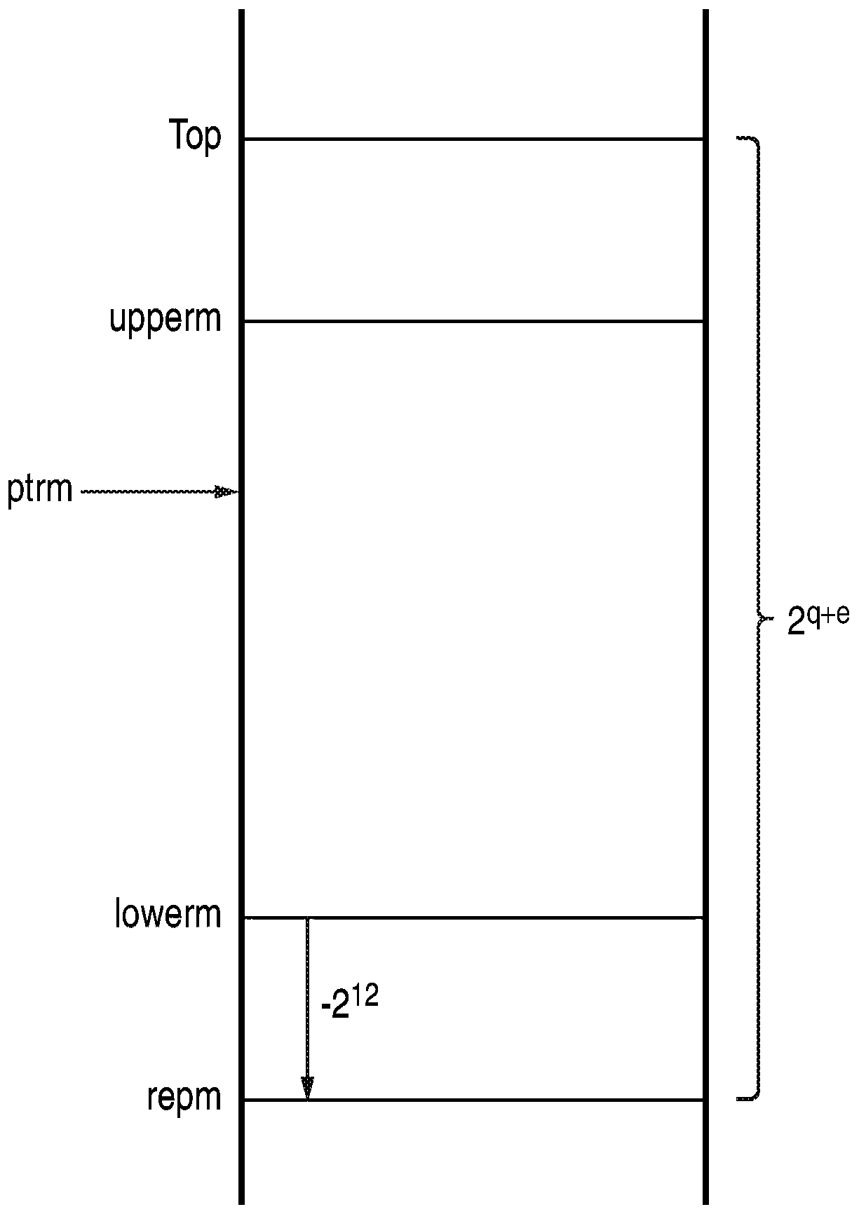
[0016] According to an example configuration, there is provided a data processing apparatus for performing a check on whether a value falls between 0 and 2 m lower bound between 0 and 2 m The determination within the boundary defined by the upper limit between, the data processing apparatus includes: storage circuit for storing each of said lower limit and said upper limit in compressed form as a mantissa of q<m bits and a shared an exponent e, wherein the most significant m-q-e bits of said lower bound and said upper bound are equal to the most significant m-q-e bits of said value; adjustment circuitry for performing adjustments in compressed form on said lower bound and said upper bound; and boundary comparison circuitry, for performing said determination on said value using said lower bound and said upper bound in said compressed form.

[001...


PUM


Abstract

A data processing apparatus is provided, for performing a determination of whether a value falls within a boundary defined by a lower limit between 0 and 2 m and an upper limit between 0 and 2 m. Theapparatus includes storage circuitry that stores each of the lower limit and the upper limit in a compressed form as a mantissa of q < m bits and a shared exponent e. A most significant m-q-e bits ofsaid lower limit and said upper limit are equal to a most significant m-q-e bits of said value. Adjustment circuitry performs adjustments to the lower limit and the upper limit in compressed form andboundary comparison circuitry performs the determination on the value using the lower limit and the upper limit in the compressed form.

Description

technical field [0001] This disclosure relates to bounds checking. By way of example only, the present disclosure may relate to memory bounds checking. Background technique [0002] It is often desirable to determine whether a value lies within boundaries defined by a lower bound and an upper bound. For example, in a memory system, memory may be partitioned into regions, where different processes "own" particular regions of memory. For security reasons, it is often desirable to prevent non-owning processes from accessing memory regions owned by another process. For this reason, attempts to access memory should be bounds checked in order to check whether the access is within the memory access area belonging to the currently executing process. As the memory system becomes larger, the size of the memory address also increases. So this not only increases the number of bits required to represent the memory location to be accessed, but also increases the number of bits require...

Claims


Application Information

Patent Timeline
Patent Type & Authority Applications(China)
IPC IPC(8): H03M7/24H03M7/30
CPCH03M7/24H03M7/30H03M7/3066H03M7/3091H03M7/702G06F3/0626G06F3/0622G06F3/0625G06F3/0638G06F3/0673G06F7/02G06F7/50G06F12/1416G06F2212/1052
Inventor 丹尼尔·阿鲁拉杰格雷姆·彼得·巴尔内斯李·埃文·艾森加里·艾伦·戈尔曼
Owner ARM LTD
Learn More