Three-dimensional face polarization illumination and information acquisition system and method thereof
A technology of information collection and three-dimensional face, which is applied in the field of face collection, can solve the problems of image quality, ambient light, interference, etc. at the same time, and achieve the effect of eliminating glare, improving quality, and eliminating image quality degradation and instability
- Summary
- Abstract
- Description
- Claims
- Application Information
AI Technical Summary
Problems solved by technology
Method used
Image

Examples
Embodiment 1
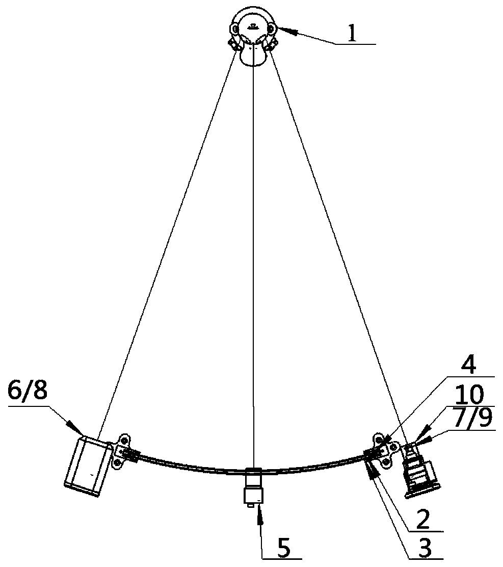
[0043] Such as image 3 As shown, a three-dimensional human face polarized illumination and information collection system includes a polarized light source, A collection camera 5, B collection camera 6, C collection camera 7, D collection camera 8, E collection camera 9, and each collection camera lens The front analyzer 10.
[0044] The polarized light source adopts arc-surface illumination, and takes the longitudinal nose bridge of the center line of the target face 1 as the dividing edge collected by the left and right cameras. Polarized light with a wide angle can make the level and details of the object plane be collected as much as possible. The polarized light source is composed of a light source plate 2 , a uniform light diffusion plate 3 and a polarizer 4 . The light source board 2 provides illumination, and the outgoing light of the light source board 2 becomes surface light parallel to the curved surface after being processed by the uniform light diffusion plate 3...
Embodiment 2
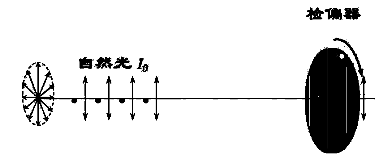
[0046] The difference between this embodiment and Embodiment 1 is that the device also includes a control terminal, and the analyzer in front of each acquisition camera lens also includes a micro-motor, and the control terminal is used to control the micro-motor working state and receive the image information collected by the acquisition camera, the analyzer is driven by a micro-motor and can rotate at a uniform speed around the center of the optical axis of the acquisition camera (its rotational speed ω is adjustable, and the polarization angle is controlled by the micro-motor driven by The control terminal can receive the driving parameters of the micro-motor), and take continuous shots so that the collected images form a series of correlation photos with target polarization information, and its illuminance meets I=Io(cosθ)^2 (θ is the polarizer and Angle between the polarization directions of the analyzer.), and it is a homogeneous image with continuous grayscale changes b...
Embodiment 3
[0048] Such as Figure 4 As shown, the difference between this embodiment and Embodiment 1 is that a grating projector 11 is provided on the left and right sides of the polarized light source, and the grating projector 11 can project a sinusoidal grating containing phase information, which can be used to calculate the The spatial depth of the face.
PUM
 Abstract
Description
Claims
Application Information
 - R&D
- Intellectual Property
- Life Sciences
- Materials
- Tech Scout
- Unparalleled Data Quality
- Higher Quality Content
- 60% Fewer Hallucinations
Browse by: Latest US Patents, China's latest patents, Technical Efficacy Thesaurus, Application Domain, Technology Topic, Popular Technical Reports.
© 2025 PatSnap. All rights reserved.Legal|Privacy policy|Modern Slavery Act Transparency Statement|Sitemap|About US| Contact US: help@patsnap.com