
Bridge expansion joint monitoring device

A monitoring device and expansion joint technology, which can be used in measurement devices, electromagnetic measurement devices, bridges, etc., can solve problems such as reducing data acquisition costs

Pending Publication Date: 2020-01-31
SHENZHEN POLYTECHNIC
View PDF0 Cites 5 Cited by
  • Summary
  • Abstract
  • Description
  • Claims
  • Application Information

AI Technical Summary

Problems solved by technology

[0004] In order to overcome the disadvantages existing in the existing bridge expansion joint detection, the present invention provides unmanned 24-hour uninterrupted detection of bridge expansion joint data, when the expansion joint exceeds the set value (for example, an earthquake in the monitoring area causes the expansion joint to be too wide , or severe overloading of vehicles leads to excessive force on the bridge, which leads to over-width expansion joints), the management staff can be given prompts to take timely countermeasures, and real-time data on expansion joints can be provided to relevant departments, and since manual inspection is not required A bridge expansion joint monitoring device that reduces the labor costs of relevant departments, reduces data acquisition costs, and provides strong technical support for bridge safety applications

Method used


Image

  • Bridge expansion joint monitoring device
  • Bridge expansion joint monitoring device
  • Bridge expansion joint monitoring device

Examples


Embodiment Construction

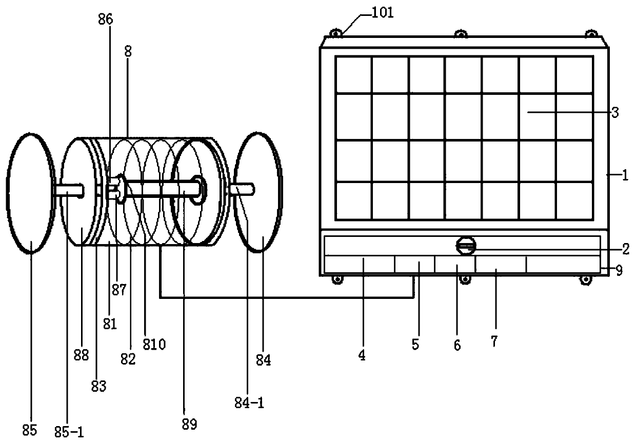
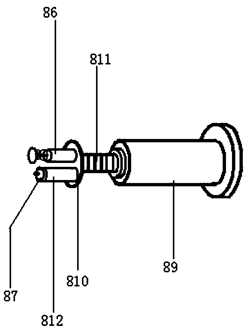
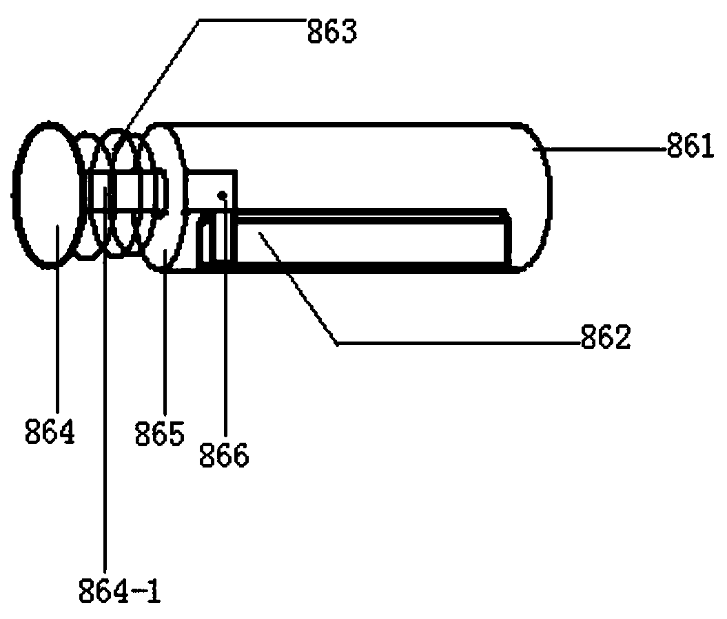
[0021] figure 1 , 2 , shown in 3, a bridge expansion joint monitoring device, including housing 1, key power switch 2, solar panel 3, storage battery 4, single-chip microcomputer module 5, GPRS module 6, short message module 7, also has detection equipment 8, Described detection equipment comprises cylinder body 81, spring 82, sliding plate 83, support plate 84, front movable plate 85, deformation amount detecting mechanism 86 and detection switch 87, and the left end outside of cylindrical cylinder body 81 has external thread, cylinder body 81 The left end is equipped with a cover 88 with a hole in the middle, the right end of the cylinder 81 is a closed structure, and the middle of the left end of the circular support plate 84 has an integrally formed circular connecting rod 84-1, and the connecting rod 84-1 The left end of the cylinder body 81 and the middle part of the right side outer end of the cylinder body 81 are integrally formed and installed together; the inner rig...


PUM


Abstract

A bridge expansion joint monitoring device comprises a shell, a key power switch, a solar cell panel, a storage battery, a single-chip microcomputer module, a GPRS module, a short message module and detection equipment; the detection equipment comprises a barrel, a spring, a sliding plate, a supporting plate, a front movable plate, a deformation detection mechanism and a detection switch, and thesupporting plate and the barrel are installed together; a supporting rod is arranged in the barrel, a supporting seat plate is arranged at the left end of the supporting rod, and the deformation detection mechanism and the detection switch are installed at the upper end and the lower end of the left side of the supporting seat plate respectively; the spring sleeves the supporting rod, and a frontconnecting rod of the front movable plate and the sliding plate are installed together; a cover is installed in the left end of the barrel; and the solar cell panel is installed at the outer end of the shell, the single-chip microcomputer module, the GPRS module and the short message module are installed on a circuit board, and the circuit board, the key power switch and the storage battery are installed in the lower end of the shell and connected with the deformation detection mechanism and the detection switch of the detection mechanism through wires. The width of a bridge expansion joint can be detected in real time.

Description

technical field [0001] The invention relates to the technical field of bridge safety monitoring equipment, in particular to a bridge expansion joint monitoring device. Background technique [0002] With the development of social economy and the needs of transportation construction, there are more and more various roads, railways, and cross-sea bridges. In bridge construction, expansion joints need to be reserved between every two adjacent bridges, that is, the distance between two bridges is required. The main function of the bridge expansion joint is to meet the deformation requirements of the bridge under thermal expansion and contraction, or other stresses, and prevent the bridge deck from being squeezed between beams and beams to cause damage to the bridge deck. The expansion joint spacing of bridges has strict requirements. Generally, the expansion of a bridge with a relatively large span is about 3 cm, and the expansion joint width is about 9 cm. In practice, the wid...

Claims


Application Information

Patent Timeline
IPC IPC(8): G01B7/14G01B7/02G01B7/16H04W4/14E01D19/06
CPCG01B7/14G01B7/02G01B7/18H04W4/14E01D19/06
Inventor 周利华王品李云杰何国坤孟宪军赵蕊张丹陈艳波
Owner SHENZHEN POLYTECHNIC
Learn More