
Elastic foil type dynamic pressure air bearing

An air bearing and foil-type technology, applied in sliding contact bearings, rotating bearings, bearings, etc., can solve the problems of high take-off speed of bearings, reduced bearing capacity, waste, etc., to improve bearing capacity and impact resistance The effect of high capacity, high limit speed and long service life

Active Publication Date: 2020-06-30
富源空气悬浮系统(潍坊)有限公司
View PDF9 Cites 0 Cited by
  • Summary
  • Abstract
  • Description
  • Claims
  • Application Information

AI Technical Summary

Problems solved by technology

[0003]In the air bearings currently used, most of the arched corrugated foils are used as the flexible support of the flat foil, but the waveform and height of the arched corrugated foil determine the performance of the bearing , if the height is too small, the bearing capacity will be reduced, and if the height is too large, the rigidity of the bearing will be deteriorated; at the same time, because the consistency of the arched corrugated foil determines the stability and reliability of the air bearing, so the arched corrugated foil The manufacturing process requirements are more stringent
In addition, the foil type dynamic pressure air bearings in the prior art mostly use one end fixed and the other end free, and the inside and outside of the bearing sleeve are concentric, resulting in a large amount of movement of the flat foil and a high take-off speed of the bearing.
Due to the working characteristics of the dynamic pressure air bearing, the rotating shaft will rub against the inner surface of the bearing flat foil during the start and stop stages. Therefore, after a certain period of operation, the bearing needs to be maintained or the flat foil replaced. The foil is usually fixed by welding. Once the foil is worn out, the entire air bearing needs to be replaced, which causes waste and increases the cost of use.

Method used


Image

  • Elastic foil type dynamic pressure air bearing
  • Elastic foil type dynamic pressure air bearing
  • Elastic foil type dynamic pressure air bearing

Examples


Embodiment Construction

[0032] The present invention will be described in further detail without limitation in conjunction with the accompanying drawings and examples below.

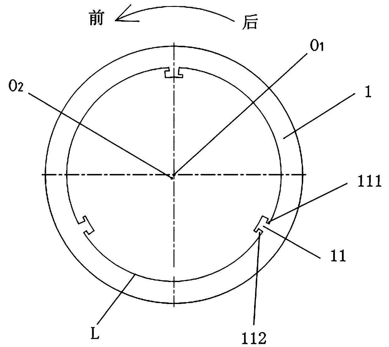
[0033] In this paper, for the convenience of description, after the bearing is matched with the shaft, the direction indicated by the shaft rotation arrow is defined as "front", and the direction opposite to "front" is defined as "rear".

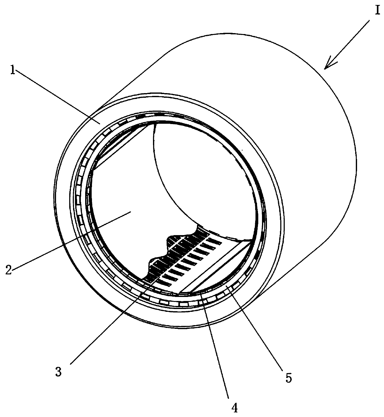
[0034] Such as figure 1 As shown, the elastic foil type dynamic pressure air bearing 1 of the embodiment of the present invention includes: a bearing sleeve 1 and an elastic support assembly arranged in the bearing sleeve 1. The elastic support assembly includes a spring sheet 3 and a flat foil sheet 2, wherein the spring The sheet 3 is located between the flat foil 2 and the inner wall surface of the bearing sleeve 1, and the spring sheet 3 has a mesh structure.

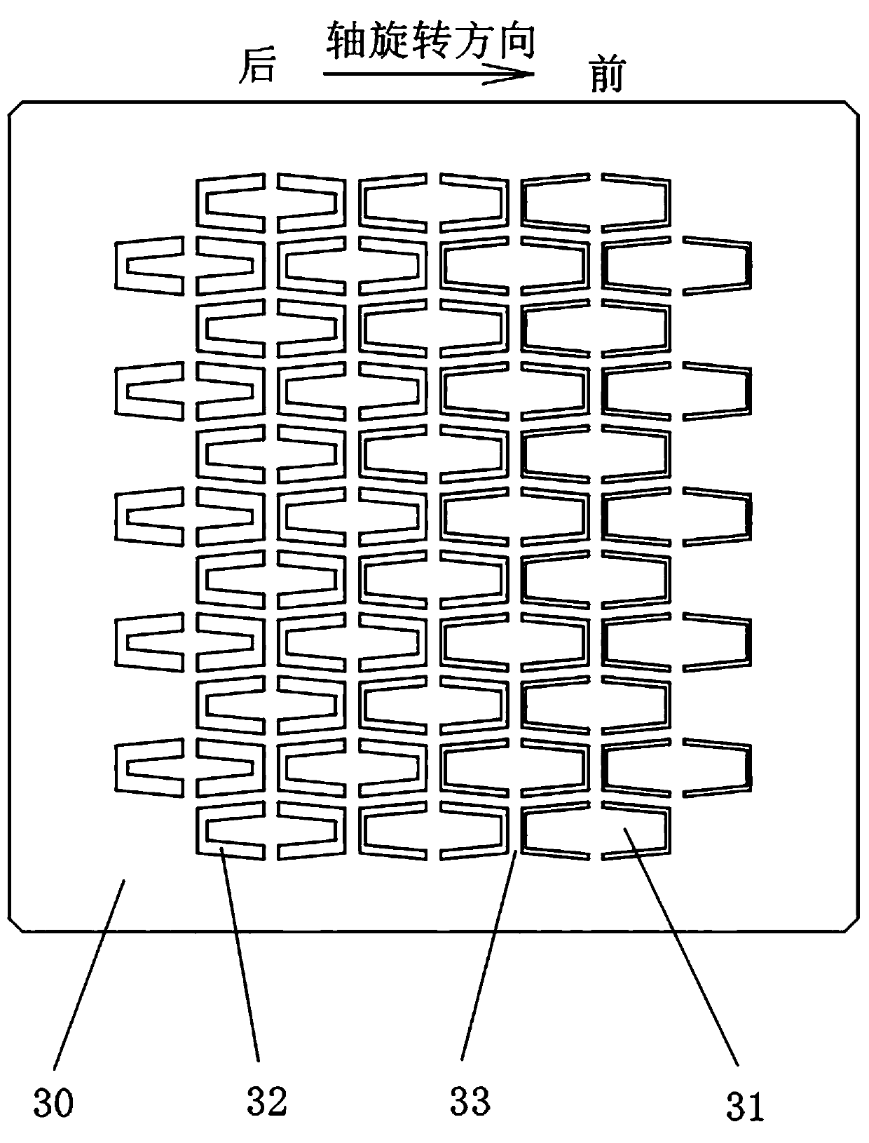
[0035] Such as image 3 As shown, it is a schematic diagram of the flattened state of the spring sheet 3. The spring sheet 3 in...


PUM


Abstract

The invention discloses an elastic foil type dynamic pressure air bearing, which comprises a bearing sleeve and an elastic support assembly arranged in the bearing sleeve, wherein the elastic supportassembly comprises a flat foil and a spring strip positioned between the flat foil and the inner wall surface of the bearing sleeve, and the spring strip is in a gradually changed net structure; the spring leaf body is provided with a plurality of supporting bodies, the front ends and the rear ends of the supporting bodies abut against the inner wall surface of the bearing sleeve, and the width ofthe front supporting body is larger than the width of the rear supporting body; the inner wall surface and the outer wall surface of the bear sleeve are eccentrically arranged; a slot is formed in the inner wall surface of the bearing sleeve, and the edge part of the elastic support assembly is inserted into the slot; the elastic foil type dynamic pressure air bearing provided by the invention isprovided with an air wedge surface, so that a lower take-off rotating speed can be obtained at a low speed, and the elastic foil type dynamic pressure air bearing is more stable and has a higher limit rotating speed at a high speed; the spring strip replaces an arched wave foil, and the bearing capacity and impact resistance of the bearing are significantly improved; the elastic support assemblyis inserted into the bearing sleeve, so that the bearing is easier to maintain and has longer service life.

Description

technical field [0001] The invention relates to the technical field of air bearings, in particular to an elastic foil type dynamic pressure air bearing. Background technique [0002] Bearings are an important part of contemporary mechanical equipment and have a very wide range of applications. With the increasing speed of rotating machinery or the requirements of special application environments, traditional bearings have become a bottleneck restricting the development of these technologies. Compared with other bearings, the dynamic pressure air bearing has the characteristics of no lubrication, high working speed, small mechanical loss, low maintenance cost and good stability, and is widely used. [0003] In the air bearings currently used, most of the arched corrugated foils are used as the flexible support of the flat foil, but the waveform and height of the arched corrugated foil determine the performance of the bearing. If the height is too small, the bearing capacity ...

Claims


Application Information

Patent Timeline
Patent Type & Authority Patents(China)
IPC IPC(8): F16C17/00F16C33/04
CPCF16C17/00F16C33/04
Inventor 陈良刘伟王新明许全亮
Owner 富源空气悬浮系统(潍坊)有限公司
Learn More