
Control method and device of car intelligent type digital electrically controlled air brake valve

A technology of air brake valve and control method, which is applied in the direction of brake transmission, brake, vehicle parts, etc., can solve the problem of control time lag, balance, affecting the accuracy and reliability of the car, and the inability to brake the car in an emergency Accurate control of strength and other issues, to achieve the effect of precise control of time lag and reduction of time lag

Active Publication Date: 2020-01-31
东莞市粤熙实业有限公司
View PDF6 Cites 0 Cited by
  • Summary
  • Abstract
  • Description
  • Claims
  • Application Information

AI Technical Summary

Problems solved by technology

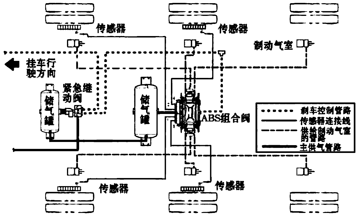
[0008] The above-mentioned patent inputs the control air through the normally open channel of the solenoid valve, outputs the control air through the normally closed channel of the solenoid valve, controls the input and output of the brake air, and then controls the brake control air signal output by the brake master cylinder. It can solve the matching problem of the automatic control system to a certain extent, but there are still some limitations in the existing technology, because the control of the control gas is only realized through the normally open and normally closed channels of a solenoid valve, so it only It is possible to brake the car through the input and output of the brake gas, but it cannot solve the problems of time lag and balance in the control of the car brake, and it cannot accurately control the emergency braking force of the car, which affects the braking performance of the car. accuracy, and reliability

Method used


Image

  • Control method and device of car intelligent type digital electrically controlled air brake valve
  • Control method and device of car intelligent type digital electrically controlled air brake valve
  • Control method and device of car intelligent type digital electrically controlled air brake valve

Examples


Embodiment Construction

[0048] The following will clearly and completely describe the technical solutions in the embodiments of the present invention with reference to the accompanying drawings in the embodiments of the present invention. Obviously, the described embodiments are only some, not all, embodiments of the present invention. Based on the embodiments of the present invention, all other embodiments obtained by persons of ordinary skill in the art without making creative efforts belong to the protection scope of the present invention.

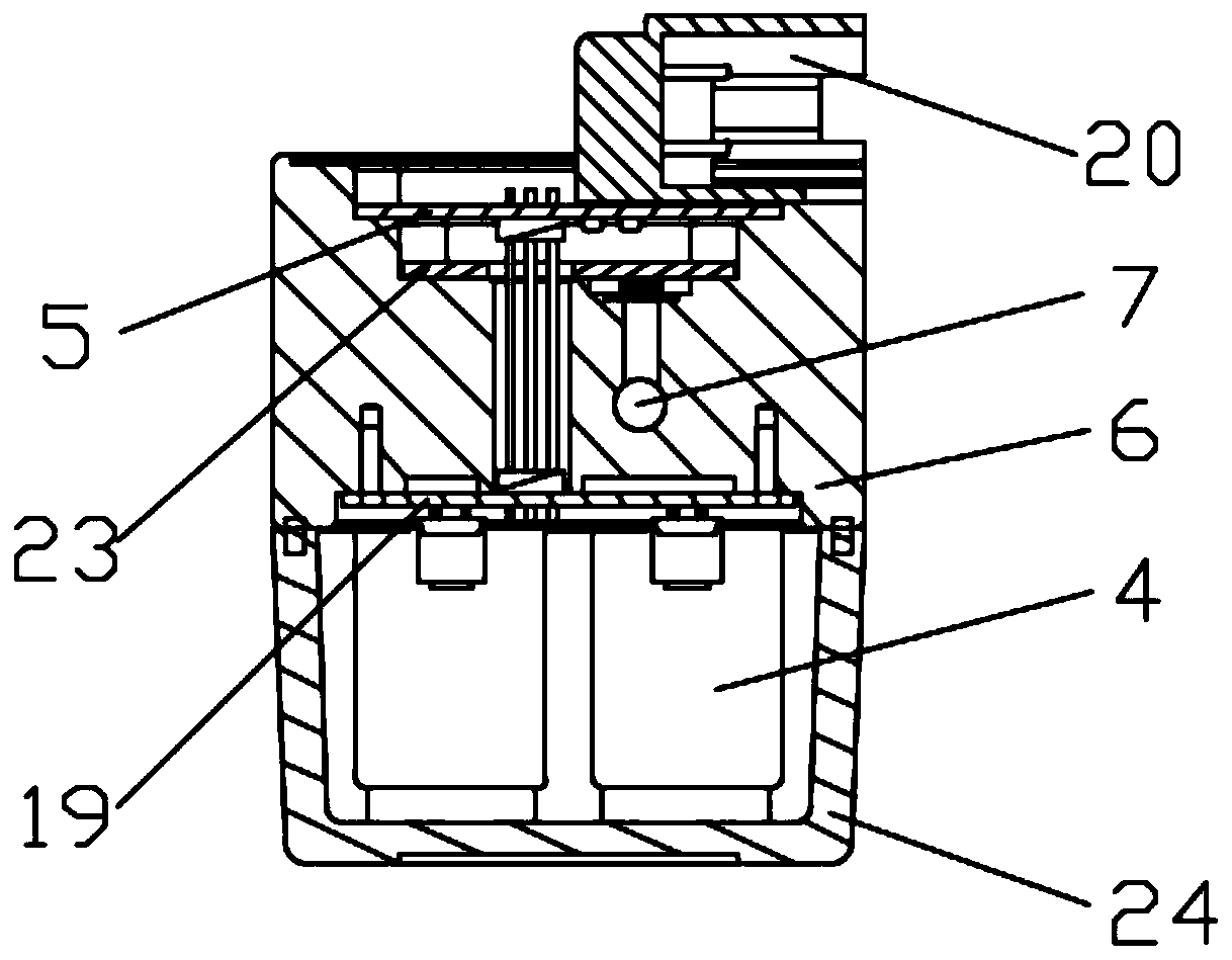
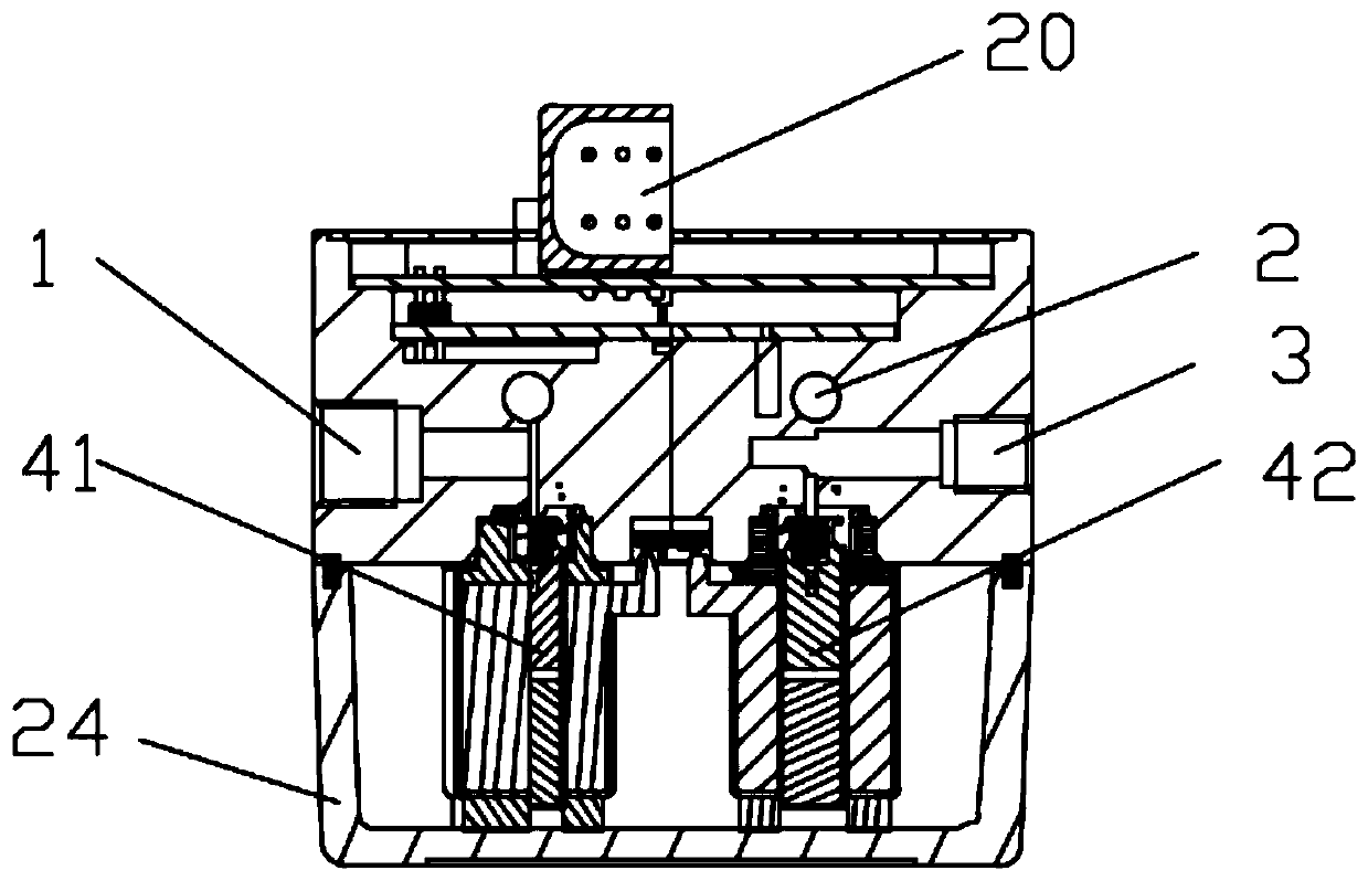
[0049] Referring to the accompanying drawings, the automobile intelligent digital electronically controlled air brake valve control method provided in this embodiment includes the following steps:

[0050] (1) An automobile intelligent digital electronically controlled air brake valve is installed on the car, which includes a central processing unit and one or more sets of adjustable air circuits that can work independently, and each group of adjustable air cir...


PUM


Abstract

The invention discloses a control method of a car intelligent type digital electrically controlled air brake valve. The method comprises the following steps that firstly, the car intelligent type digital electrically controlled air brake valve is arranged on a car; secondly, a car driving monitoring device carries out continuous monitoring on surrounding in the car driving process, a central processor judges whether active brake needs to be carried out or not through the data detected by the outer car driving monitoring device and analysis processing; and thirdly, when it is judged that activebraking needs, according to the information detected by the car driving monitoring device, through a built-in logic program, operation is carried out, opening and closing time point and frequency control brake parameter signals of air inlet electromagnetic valves and exhaust electromagnetic valves of adjustable air paths, the brake parameter signals are sent, execution is carried out through theelectromagnetic valves, and pressure gas and work pressure, input and exhausted from corresponding brake devices, of the air paths are precisely controlled, and precise control over the magnitude, speed and continuous time of brake force of the brake devices is achieved.

Description

technical field [0001] The invention relates to the technical field of automobile braking, in particular to an automobile intelligent digital electronic control air brake valve control method and device. Background technique [0002] Automobile brakes are the braking devices of automobiles. The brakes used in automobiles are almost all friction type, which can be divided into two categories: drum type and disc type. The rotating element in the friction pair of the drum brake is the brake drum, and its working surface is a cylindrical surface; the rotating element of the disc brake is the rotating brake disc, with the end surface as the working surface. Automobile brakes refer to the components that generate force (braking force) that hinders the movement or movement tendency of the vehicle, including retarding devices in the auxiliary braking system. [0003] The power emergency braking system controlled by air pressure of high-pressure gas has been widely used in commercia...

Claims


Application Information

Patent Timeline
Patent Type & Authority Applications(China)
IPC IPC(8): B60T13/68
CPCB60T13/683
Inventor 雷明陈卫东何志忠
Owner 东莞市粤熙实业有限公司
Learn More