
A grinding device for valve processing

A valve and pressing device technology, which is applied in the direction of grinding drive device, grinding/polishing safety device, metal processing equipment, etc., can solve the problems of inconvenient fixing, difficult cleaning of waste, inconvenient fixing of processed objects, etc. Good effect, avoid dust flying, enhance the effect of flexibility

Active Publication Date: 2020-09-22
KEVINS FLUID CONTROL (JIANGSU) CO LTD
View PDF9 Cites 0 Cited by
  • Summary
  • Abstract
  • Description
  • Claims
  • Application Information

AI Technical Summary

Problems solved by technology

[0004] The object of the present invention is to provide a grinding device for valve processing to solve the problem that most of the current grinding devices for valve processing proposed in the above background technology are only for processing the valve stem or valve body, and it is not convenient for one device to realize all of them. It is fixed, and it is not convenient to fix the processed objects of different sizes. In addition, the waste generated during the processing is not easy to clean up, and it is not convenient to cool down the polished part.

Method used


Image

  • A grinding device for valve processing
  • A grinding device for valve processing
  • A grinding device for valve processing

Examples


Embodiment Construction

[0027] The following will clearly and completely describe the technical solutions in the embodiments of the present invention with reference to the accompanying drawings in the embodiments of the present invention. Obviously, the described embodiments are only some, not all, embodiments of the present invention. Based on the embodiments of the present invention, all other embodiments obtained by persons of ordinary skill in the art without making creative efforts belong to the protection scope of the present invention.

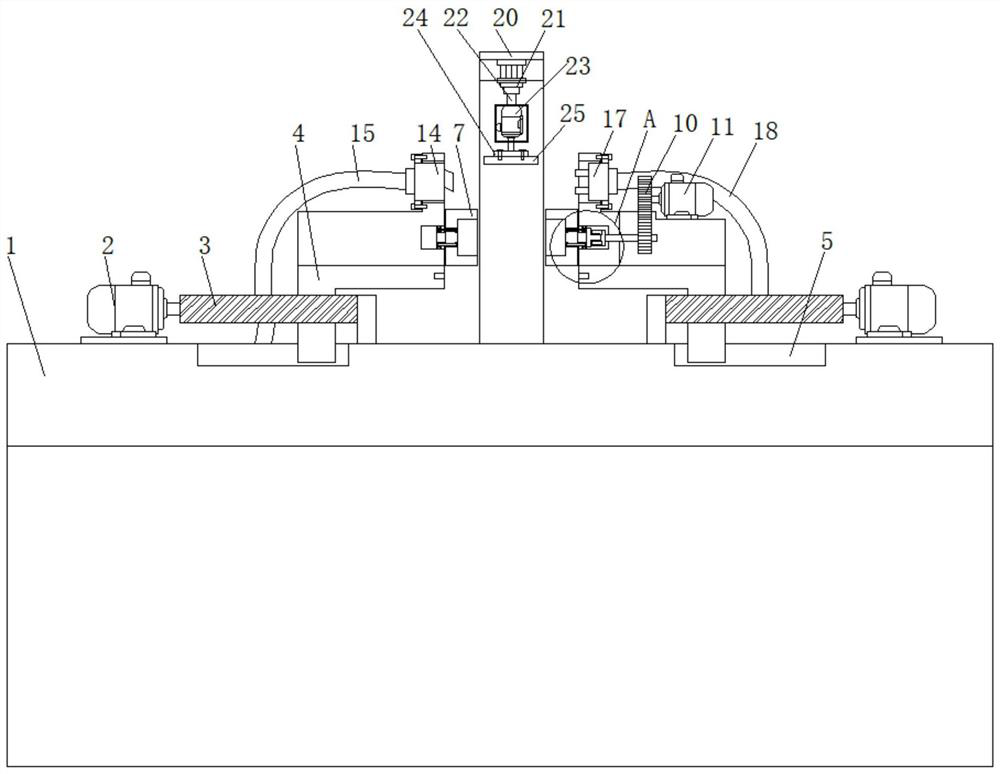
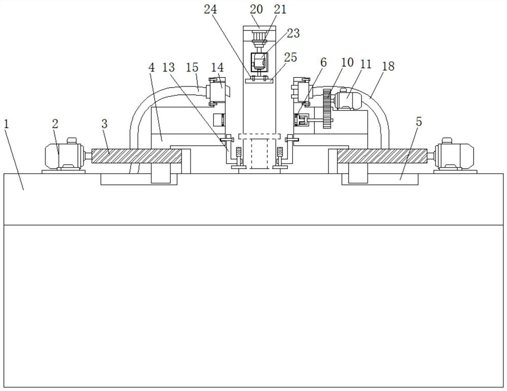
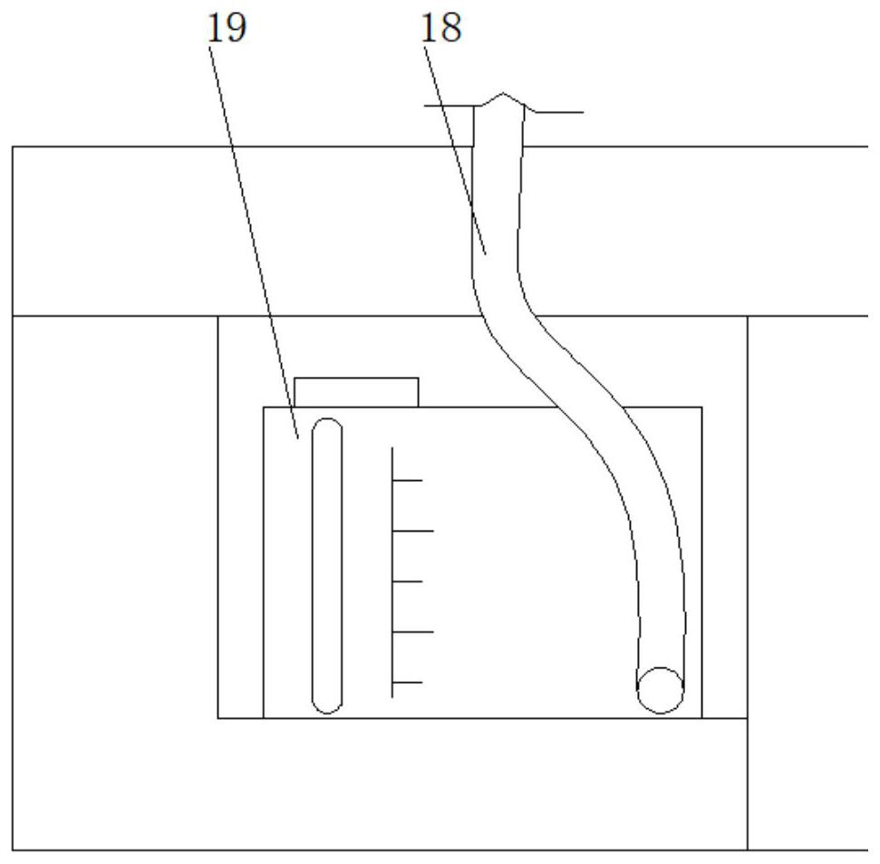
[0028] see Figure 1-6 , the present invention provides a technical solution: a grinding device for valve processing, according to figure 1 , Figure 4 and Figure 5 As shown, the left and right sides of the console 1 are provided with a first motor 2, and the inner side of the first motor 2 is connected with the threaded rod 3, the threaded rod 3 runs through the lower end of the support platform 4, and the bottom of the support platform 4 is arranged on I...


PUM


Abstract

The invention discloses a grinding device for valve machining. The grinding device comprises an operation table, a gear, a second threaded hole, a pressing device, a dust suction cover and a spray head, wherein first motors are arranged on the left side and the right side of the operation table; a threaded rod penetrates through the lower ends of supporting tables; connecting pieces are arranged in the middles of the inner side surfaces of the supporting tables; the gear is arranged on a fixing sleeve on the right side; the gear is connected with a second motor through a gear set; the second threaded hole is formed in the inner side surface of the supporting table; the dust suction cover is mounted at the upper end of the supporting table on the left side; the spray head is mounted at theupper end of the supporting table on the right side; a supporting frame is arranged in the middle of the upper surface of the operation table; and a mounting plate is arranged below a third motor. According to the grinding device for valve machining, the supporting tables can move left and right under the action of the first motors and the threaded rod, so that the distance between the supportingtables on the two sides can be conveniently adjusted, and after the fixing sleeve or the pressing device is selected to be mounted, valve rods or valve bodies with different sizes can be convenientlyfixed.

Description

technical field [0001] The invention relates to the technical field of valve processing, in particular to a grinding device for valve processing. Background technique [0002] A valve is a mechanical device that controls the flow, flow direction, pressure, temperature, etc. of the flowing fluid medium. The valve is a basic component in the piping system. The valve body and valve stem are important components of the valve. When processing it, it is necessary Grinding it requires the use of a grinding device for valve processing. [0003] At present, most of the grinding devices for valve processing are only aimed at processing the valve stem or valve body, and it is not convenient for one device to fix them all, so that the use of the device is limited, and it is not convenient to fix processed objects of different sizes , In addition, the waste chips generated during the processing process are not easy to clean, resulting in a poor processing environment, and it is not conv...

Claims


Application Information

Patent Timeline
Patent Type & Authority Patents(China)
IPC IPC(8): B24B19/00B24B41/04B24B47/12B24B47/20B24B47/22B24B55/03B24B55/04B24B55/06
CPCB24B19/00B24B41/04B24B47/12B24B47/20B24B47/22B24B55/03B24B55/04B24B55/06
Inventor 卓振基王桃胜卓志森何崇林许新城孙爱军
Owner KEVINS FLUID CONTROL (JIANGSU) CO LTD
Learn More