
Moving base plate for machine tool

A base plate and machine tool technology, which is applied to metal processing machinery parts, large fixed members, metal processing equipment, etc., can solve the problems of inability to install machine tools, lack of portability and versatility, and achieve saving manpower and material resources, convenient operation, and use convenient effect

Inactive Publication Date: 2020-01-31
TAIZHOU ZHUIRI GEAR
View PDF0 Cites 2 Cited by
  • Summary
  • Abstract
  • Description
  • Claims
  • Application Information

AI Technical Summary

Problems solved by technology

[0002] Ordinary machine tool baseplates are fixed together with the machine body, and cannot be installed on other machine tools, which cannot achieve portability and versatility. Therefore, a mobile baseplate for machine tools is proposed

Method used


Image

  • Moving base plate for machine tool
  • Moving base plate for machine tool
  • Moving base plate for machine tool

Examples


Embodiment Construction

[0015] Below in conjunction with accompanying drawing and specific embodiment the present invention is described in further detail:

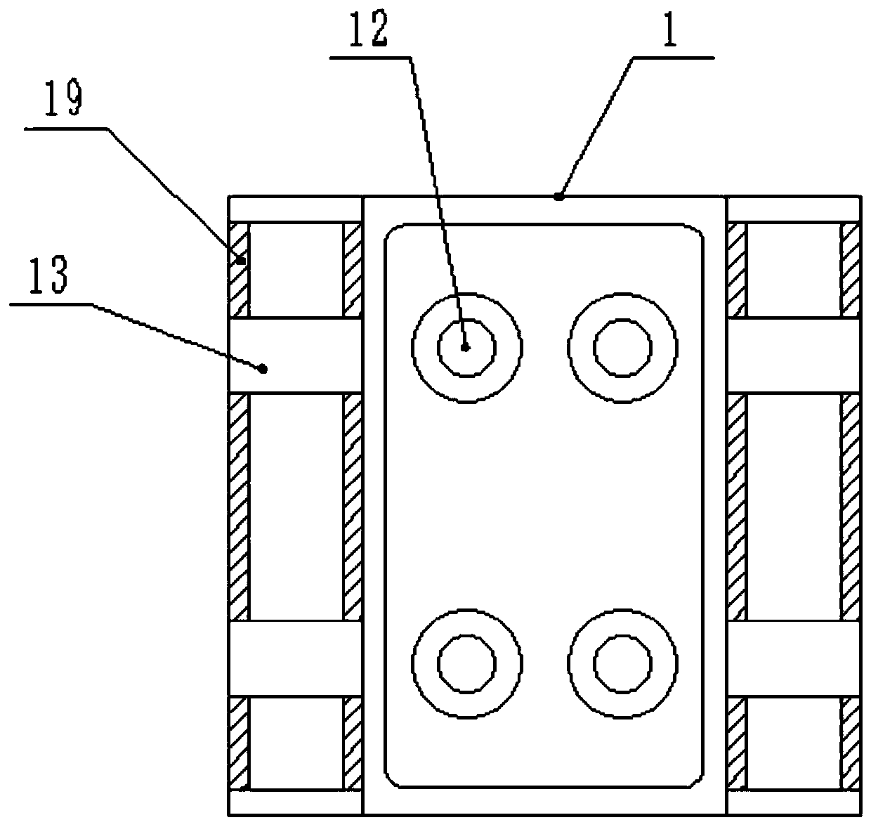
[0016] Such as Figure 1-3 As shown, a mobile base plate of a machine tool includes a support plate 1, a mechanical jack 2, a fine threaded rod 7, a moving wheel 12, a lead screw 15 and an adjustment sleeve 15, and two mechanical jacks 2 are connected by bolts under the support plate 1. Two bottom plates 3 are fixed at the bottom of the two mechanical jacks 2, and the two mechanical jacks 2 have the function of supporting the CNC machine tool. Manually adjusting the length of the mechanical jack 2 can change the height of the CNC machine tool and facilitate adjustment to a suitable position. Above the support plate 1 The fuselage 4 with the CNC machine tool is placed, two telescopic fixed columns 5 are fixed on both sides of the fuselage 4, and the two telescopic fixed columns 5 are respectively welded on the two fixed frames 6, and the two tele...


PUM


Abstract

The invention discloses a moving base plate for a machine tool. Two mechanical jacks are connected to the lower part of a support plate through bolts, a machine body of a numerical control machine tool is placed on the upper part of the support plate, two telescopic fixing columns are fixed to both sides of the machine body, the two telescopic fixing columns are welded to two fixing frames correspondingly, the two telescopic fixing columns are internally connected with fine threaded rods correspondingly, fixing sleeve disks are connected to the fine threaded rods in a threaded mode, a connection plate is welded to the lower part of the support plate, and four moving wheels are installed on the lower part of the connection plate. According to the moving base plate, the mechanical jacks havethe function of supporting the numerical control machine tool, the height of the machine body can be adjusted by adjusting the lengths of the mechanical jacks, when the lengths of the mechanical jacks are shortened to a certain extent, the moving wheels are in contact with the ground, under driving of the moving wheels, the numerical control machine tool is convenient to move, an adjusting sleevedisk is rotated, a lead screw can drive the machine body to move through moving nuts, and thus the position of the machine body on the support plate is adjusted.

Description

technical field [0001] The invention relates to the field of mechanical processing, in particular to a movable bottom plate of a machine tool. Background technique [0002] Ordinary machine tool bottom plate and machine body are fixed together, and cannot be installed on other machine tools, and portability and versatility cannot be realized. Therefore, a mobile bottom plate of machine tool is proposed. Contents of the invention [0003] In order to solve the above existing problems, the present invention provides a movable base plate of a machine tool, which can solve the problems mentioned in the background art. [0004] The present invention is realized through the following technical solutions: [0005] A mobile bottom plate of a machine tool, comprising a support plate, a mechanical jack, a fine threaded rod, a moving wheel, a lead screw and an adjustment sleeve, two mechanical jacks are connected by bolts under the support plate, and two mechanical jacks are fixed a...

Claims


Application Information

Patent Timeline
Patent Type & Authority Applications(China)
IPC IPC(8): B23Q1/01
CPCB23Q1/01
Inventor 蔡晨炜周文君
Owner TAIZHOU ZHUIRI GEAR
Learn More