
Composite floor slab

A technology of superimposed floors and floors, applied to floors, structural elements, building components, etc., can solve the problems of low production efficiency, high production costs of laminated floors, mold processing costs and high turnover costs

Pending Publication Date: 2020-01-24
HUNAN YUANDA ENG DESIGN CO LTD
View PDF0 Cites 2 Cited by
  • Summary
  • Abstract
  • Description
  • Claims
  • Application Information

AI Technical Summary

Problems solved by technology

[0004] Based on this, it is necessary to provide an improved solution for the low production efficiency of the laminated floor slabs with protruding steel bars, high mold processing costs and high turnover costs, which lead to high production costs of the laminated floor slabs. Composite slabs with the above defects

Method used


Image

  • Composite floor slab
  • Composite floor slab
  • Composite floor slab

Examples


Embodiment Construction

[0021] In order to facilitate the understanding of the present invention, the present invention will be described more fully below with reference to the associated drawings. Preferred embodiments of the invention are shown in the accompanying drawings. However, the present invention can be embodied in many different forms and is not limited to the embodiments described herein. On the contrary, these embodiments are provided to make the understanding of the disclosure of the present invention more thorough and comprehensive.

[0022] It should be noted that when an element is referred to as being “fixed” to another element, it can be directly on the other element or there can also be an intervening element. When an element is referred to as being "connected to" another element, it can be directly connected to the other element or intervening elements may also be present. The terms "vertical," "horizontal," "left," "right," and similar expressions are used herein for purposes ...


PUM


Abstract

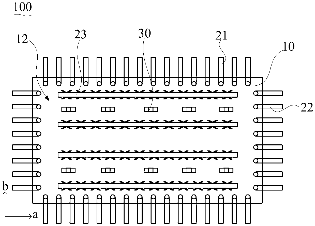
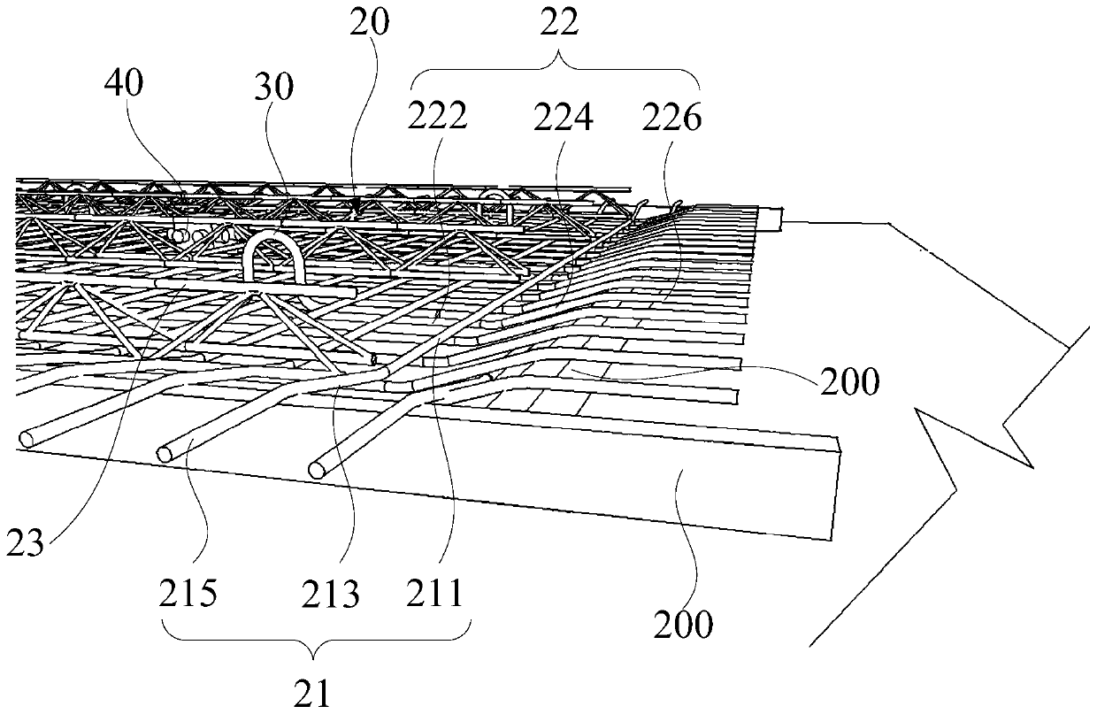
The invention discloses a composite floor slab. The composite floor slab comprises a prefabricated layer and a rebar assembly embedded into the prefabricated layer; the rebar assembly comprises a plurality of first backstraps and a plurality of second backstraps, the first backstraps are arranged at intervals in the first direction, each first backstrap is perpendicular to the first direction, thesecond backstraps are arranged at intervals in the second direction, and each second backstrap is perpendicular to the second direction; one or more ends of each first backstrap and / or each second backstrap are obliquely arranged relative to the plane formed by the first direction and the second direction, and penetrate through the top surface edge of the prefabricated layer. Because one or moreends of each first backstrap and / or each second backstrap are obliquely arranged relative to the plane formed by the first direction and the second direction, and penetrate through the top surface edge of the prefabricated layer of the composite floor slab, penetrating holes for the first backstraps or the second backstraps to penetrate do not need to be formed in the flange of a mold, thus the processing cost and turnover cost of the mold are lowered, and the production cost of the composite floor slab is further lowered.

Description

technical field [0001] The invention relates to the field of prefabricated buildings, in particular to a laminated floor slab. Background technique [0002] With the development of modern industrial technology, building houses can be manufactured in batches and in sets, just like machine production. Just transport the prefabricated building components to the construction site and assemble them. Because the construction speed of prefabricated building is fast, and production cost is relatively low, popularizes rapidly. [0003] In the production of prefabricated components of prefabricated floor slabs, since the end of the general laminated floor has protruding steel bars, it is necessary to open holes for the protruding steel bars to pass through at the corresponding positions of the ribs of the forming mold. However, different sizes of laminated slabs have different positions of protruding steel bars, and specific mold ribs need to be manufactured, which affects productio...

Claims


Application Information

Patent Timeline
Patent Type & Authority Applications(China)
IPC IPC(8): E04B5/17E04C5/01
CPCE04B5/17E04C5/01
Inventor 张剑欧阳信李志荣罗权国聂聪
Owner HUNAN YUANDA ENG DESIGN CO LTD
Learn More