
Clamp lifting supporting table

A technology of support table and fixture, applied in the direction of manufacturing tools, auxiliary devices, auxiliary welding equipment, etc., can solve the problems of inconvenient processing of workpieces with different heights, bruises of workpieces to be processed, and non-adjustable heights.

Active Publication Date: 2020-01-24
重庆经纬驰汽车部件有限公司
View PDF9 Cites 1 Cited by
  • Summary
  • Abstract
  • Description
  • Claims
  • Application Information

AI Technical Summary

Problems solved by technology

[0004] The present invention aims to solve the problems that the current fixtures are inconvenient to process workpieces with different heights due to non-adjustable heights and the workpieces to be processed are easily damaged. Aiming at the above-mentioned deficiencies in the prior art, a clamp lifting support is provided tower

Method used


Image

  • Clamp lifting supporting table
  • Clamp lifting supporting table
  • Clamp lifting supporting table

Examples


Embodiment Construction

[0026] In order to make the technical means, creative features, goals and functions achieved by the present invention clearer and easier to understand, the present invention will be further elaborated below in conjunction with the accompanying drawings and specific embodiments:

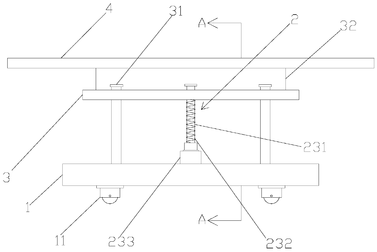
[0027] A fixture lifting support table, such as figure 1 As shown, it includes: a base 1 with moving wheels 11 installed at the bottom, a lifting mechanism 2, a moving plate 3, and a support plate 4 installed on the moving plate 3, and several connecting rods are connected between the moving plate 3 and the supporting plate 4 31. During installation, the upper part of the support plate 4 is used for installing fixtures and placing workpieces to be processed.

[0028] Among them, such as figure 2 As shown, the lifting mechanism 2 is arranged in the middle of the base 1, and is located between the base 1 and the moving plate 3. The lifting mechanism 2 includes a moving part 21, a first cushioning comp...


PUM


Abstract

The invention provides a clamp lifting supporting table which comprises a base with the bottom provided with moving wheels, a lifting mechanism, a moving plate and a supporting plate installed on themoving plate. Multiple connecting rods are connected between the moving plate and the supporting plate. The lifting mechanism is arranged between the base and the moving plate. The lifting mechanism comprises a moving part, first cushioning parts and second cushioning parts connected to the two sides of the first cushioning parts. One end of the moving part is connected with the moving plate, andthe other end of the moving part is connected with the first cushioning parts. The moving part comprises a connecting part, moving sleeves and a fixing rod, the connecting part is overall in an inverted Y shape, one end of the connecting part is connected with the moving plate, and the other two ends of the connecting part are connected with the moving sleeves arranged on the fixing rod in a sleeving manner. In addition, the moving sleeves can move on the fixing rod so as to compress the first cushioning parts on the two sides, and therefore the connecting part can be buffered by the first cushioning parts and the second cushioning parts when being pressed towards the fixing rod.

Description

technical field [0001] The invention relates to the technical field of equipment for the production of auto parts, in particular to a lifting support platform for clamps. Background technique [0002] Fixture refers to the device used to fix the processing object in the process of mechanical manufacturing, so that the processing object has the correct position, and then the fixed processing object is subjected to construction or inspection. When the workpiece to be processed is processed on the assembly line, it needs to be positioned and clamped on the fixture of each process to process. [0003] In the prior art, the lower part of the fixture is a movable base. However, in the production process of small workshops, the structures and sizes of workpieces to be processed are different, and the heights are also different. At this time, the height of the fixture cannot be adjusted. The product is relatively difficult. In addition, when the operator hits the workpiece fixed by...

Claims


Application Information

Patent Timeline
Patent Type & Authority Applications(China)
IPC IPC(8): B23K37/04
CPCB23K37/0461
Inventor 夏卫
Owner 重庆经纬驰汽车部件有限公司
Learn More