Arc chamfering device for steel plate machining

An arc chamfering and steel plate technology, applied in the directions of feeding devices, positioning devices, storage devices, etc., can solve the problems of low work efficiency, unsuitable for large steel plates, affecting the overall quality of steel plates, etc., to achieve good chamfering effect, avoid Sliding, high-efficiency effect

Inactive Publication Date: 2020-01-24
安徽跨宇钢结构网架工程有限公司
View PDF10 Cites 1 Cited by
  • Summary
  • Abstract
  • Description
  • Claims
  • Application Information

AI Technical Summary

Problems solved by technology

[0002] The steel plate is a flat steel material that is poured with molten steel and pressed after cooling. The steel plate is flat and rectangular, and can be directly rolled or cut from a wide steel strip. With the development of science and technology and industry, the steel plate Chamfering has high requirements. At present, most factories still use hand-held chamfering tools to chamfer the steel plate side by side. Not only is the work efficiency low, but also the chamfering effect is uneven due to the technical level of the workers. It affects the overall quality of the steel plate, and most general chamfering machines are aimed at cylindrical materials. For example, the application number 201810531059.1 published a "chamfering processing machine", including a working platform, a chamfering cutting mechanism, a feeding mechanism and an upper Material manipulator, this kind of equipment can only be used for chamfering processing of cylindrical materials, and it is not suitable for large steel plates. Therefore, we propose an arc chamfering device for steel plate processing

Method used


Image

  • Arc chamfering device for steel plate machining
  • Arc chamfering device for steel plate machining
  • Arc chamfering device for steel plate machining

Examples


Embodiment Construction

[0019] In order to make the technical means, creative features, achievement goals and effects realized by the present invention easy to understand, the present invention will be further described below with reference to the specific embodiments.

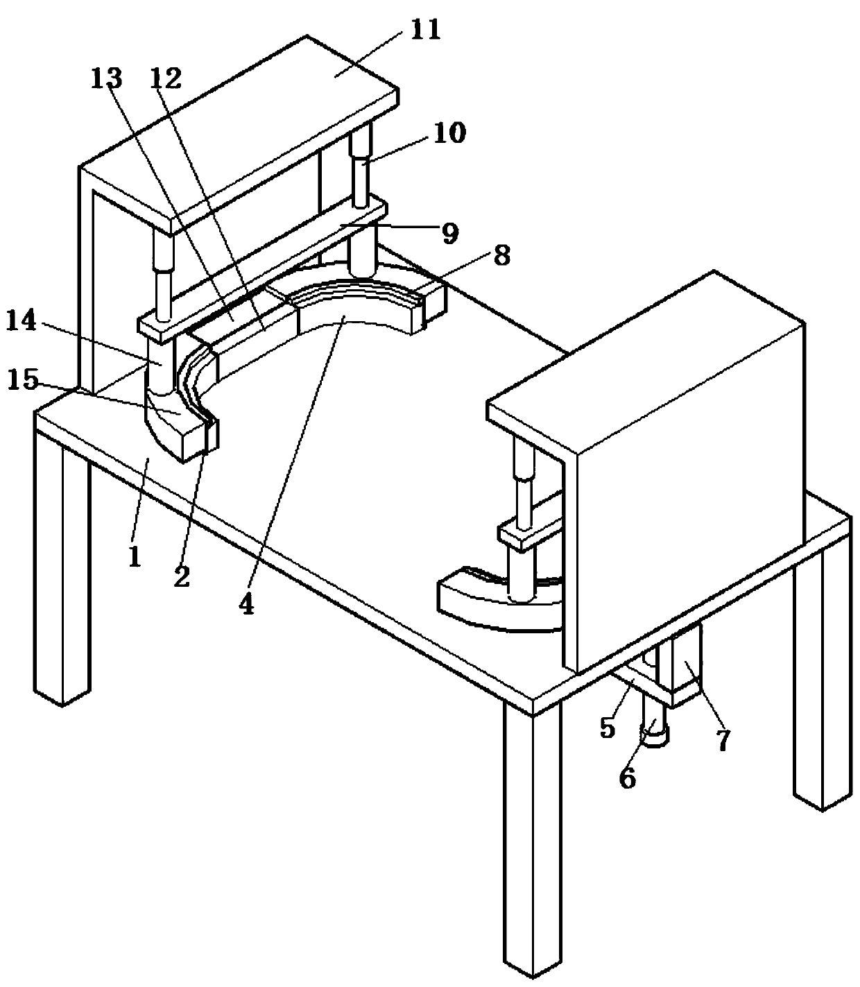
[0020] like Figures 1 to 4 As shown in the figure, this embodiment provides a circular arc chamfering device for steel plate processing, including a workbench, the top of the workbench is provided with mounting brackets at both ends, and the top of the mounting bracket is fixedly installed with chamfering cutting The inner side of the chamfering cutting assembly is provided with a clamping assembly installed on the worktable, and the outer side of the clamping assembly and between the chamfering cutting assemblies is provided with a driving assembly installed on the worktable.

[0021] Further, the mounting frame has a longitudinal section with a type bracket.

[0022] Further, the chamfering cutting assembly includes a cylinder ...


PUM


Abstract

The invention discloses an arc chamfering device for steel plate machining. The arc chamfering device comprises a workbench, wherein mounting frames are arranged at the two ends of the top of the workbench, chamfering cutting assemblies are fixedly mounted on the mounting frames, clamping assemblies mounted on the workbench are arranged on the inner side of the chamfering cutting assemblies, and driving assemblies mounted on the workbench are arranged on the outer side of the clamping assemblies and located between the chamfering cutting assemblies. According to the arc chamfering device, thetail end of a transition supporting plate is fixedly connected with a telescopic plate connected with the bottom of the workbench through a connecting frame, when the telescopic plate is used, a mainpressing plate is pushed up by a rotating adjusting screw rod to drive an arc-shaped side pressing plate to jack up at the same time, the steel plate is placed between the arc-shaped side pressing plate and the workbench, the main pressing plate is put down again through rotating the adjusting screw rod, so that the arc-shaped side pressing plate is driven to clamp the steel plate at the same time, an air cylinder drives a connecting plate to drive an arc-shaped blade to move downwards, meanwhile, an arc-shaped pressing block presses the arc-shaped side pressing plate while cutting, and the steel plate is prevented from sliding during cutting.

Description

technical field [0001] The invention relates to a circular arc chamfering device for steel plate processing, belonging to the technical field of steel structure processing equipment. Background technique [0002] The steel plate is a flat steel cast with molten steel and pressed after cooling. The steel plate is flat and rectangular, which can be directly rolled or cut from a wide steel strip. Chamfering has high requirements. At present, most factories still use chamfering tools to chamfer the steel plate edge by edge. Not only is the work efficiency low, but also the effect of chamfering is uneven due to the technical level of the workers. It affects the overall quality of the steel plate, and most of the general chamfering machines are aimed at cylindrical materials. For example, the application number is 201810531059.1. A "Chamfering Machine" was announced, including a working platform, a chamfering cutting mechanism, a feeding mechanism and an upper This kind of equipm...

Claims


Application Information

Patent Timeline
Patent Type & Authority Applications(China)
IPC IPC(8): B21D28/02B21D28/14B21D43/00
CPCB21D28/002B21D28/02B21D28/14B21D43/003
Inventor 沈建东沈龙沈虎
Owner 安徽跨宇钢结构网架工程有限公司
Why Eureka
Try Eureka