
Bidirectional coupling detector and method based on rectangular waveguide

A two-way coupling, rectangular waveguide technology, used in waveguide-type devices, electrical components, connecting devices, etc., can solve the problems of complex design and assembly, large size, and inability to perform at the same time, so as to reduce installation complexity, reduce volume, and integrate high degree of effect

Active Publication Date: 2020-01-21
SOUTHWEST CHINA RES INST OF ELECTRONICS EQUIP
View PDF5 Cites 5 Cited by
  • Summary
  • Abstract
  • Description
  • Claims
  • Application Information

AI Technical Summary

Problems solved by technology

[0005] 1. Only one-way coupling detection can be realized;
[0006] 2. It can realize two-way coupling detection, but it cannot be carried out at the same time, and it needs to be switched by a switch;
[0007] 3. The two-way coupler and detector are independently designed, and then connected through the corresponding circuit structure, the size is large, and the design and assembly are more complicated

Method used


Image

  • Bidirectional coupling detector and method based on rectangular waveguide
  • Bidirectional coupling detector and method based on rectangular waveguide
  • Bidirectional coupling detector and method based on rectangular waveguide

Examples


Embodiment 1

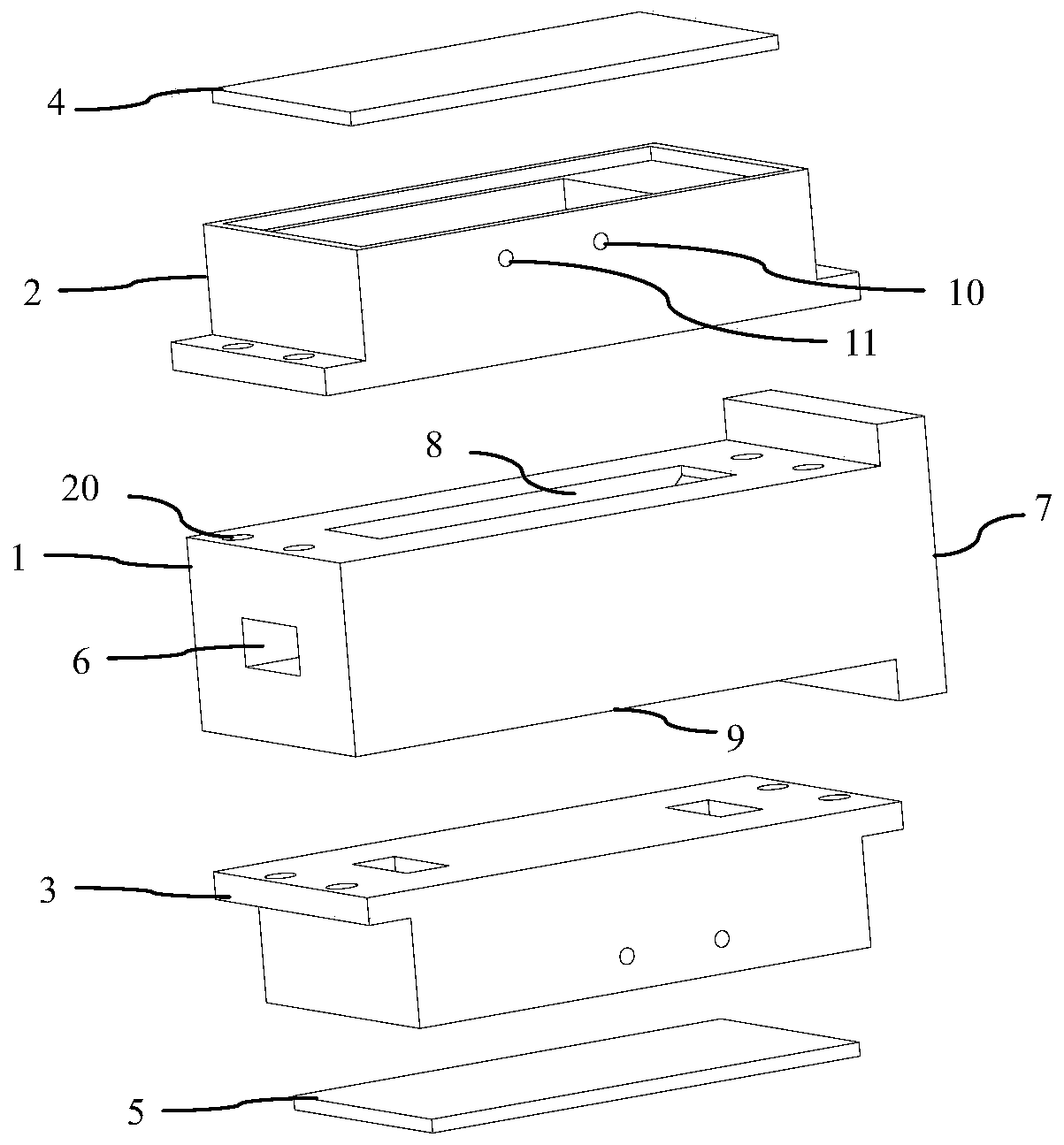
[0037] The schematic diagram of the structure of the main cavity and the detector of a bidirectionally coupled detector based on a rectangular waveguide provided by the present invention is as follows figure 1 shown. It consists of a main cavity 1 , a first side cavity 2 , a second side cavity 3 , a first cover 4 and a second cover 5 . The two ends of the main cavity 1 are the input waveguide 6 and the output waveguide 7 respectively, the two sides of the main cavity 1 are the first coupling branch 8 and the second coupling branch 9, the first side cavity 2 and the second side The cavity 3 has the same structure, and its sides are the power supply terminal 10 and the detection voltage terminal 11 of the microwave circuit.

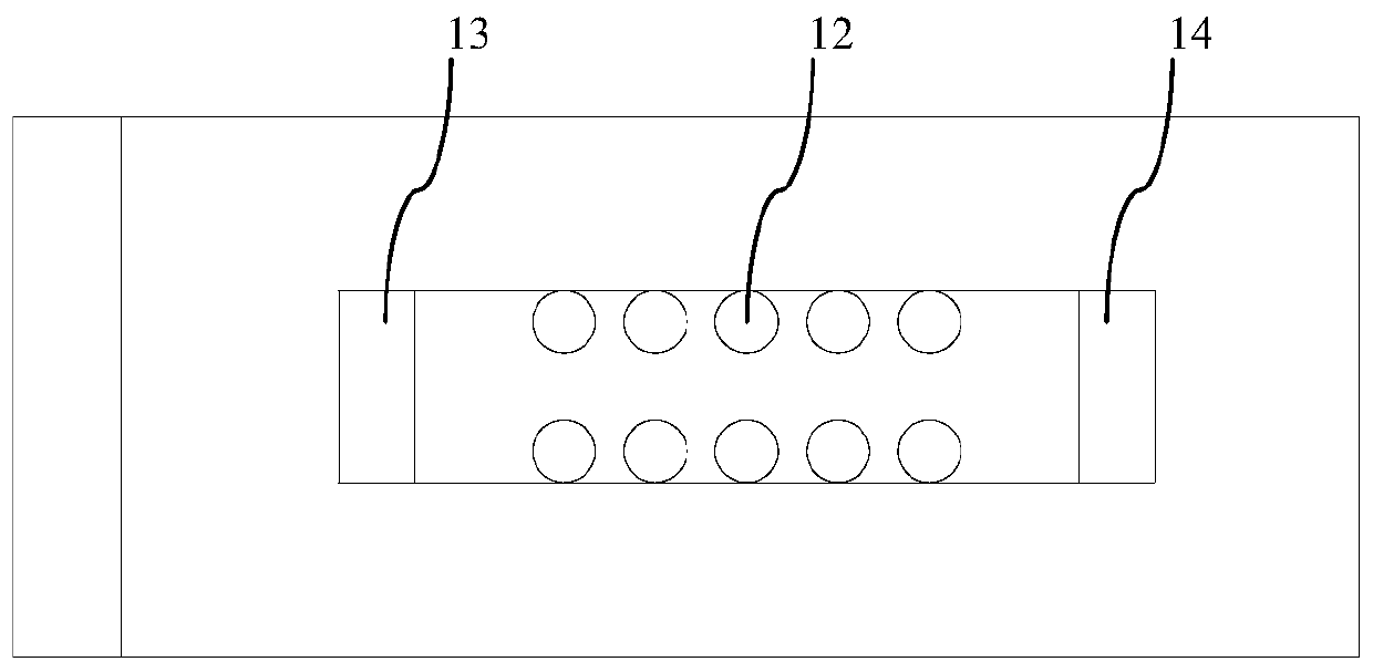
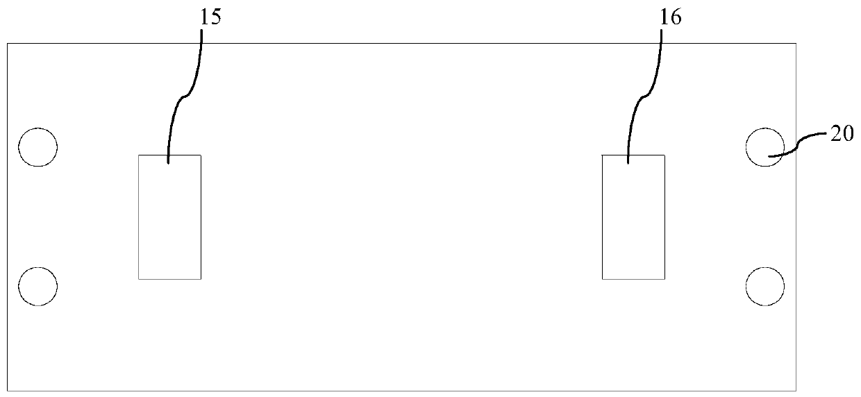
[0038] The relationship between the first coupling branch 8 and the second coupling branch 9 relative to the main cavity 1 is the same, as figure 2 Shown is a schematic diagram of setting the coupling branch surface of the main cavity, which is the first...


PUM


Abstract

The invention discloses a bidirectional coupling detector and method based on a rectangular waveguide, and relates to the technical field of bidirectional coupling detectors. The bidirectional coupling detector comprises a detector which comprises a microwave circuit, and the bidirectional coupling detector also comprises a bidirectional waveguide coupler. The bidirectional waveguide coupler comprises a main cavity, the main cavity is provided with a main path straight-through waveguide, and the two ends of the main path straight-through waveguide are an input waveguide and an output waveguiderespectively. Coupling branches are arranged on the two sides of the main path straight-through waveguide. Each coupling branch is connected with the detector. The detector also comprises side cavities. The side cavities are each provided with at least two waveguide grooves. Each waveguide groove and the coupling branch corresponding to the side cavity form a coupling port and an isolation port.The bidirectional coupling detector based on a rectangular waveguide is high in integration level. The bidirectional coupler and the detector are designed in a combined mode in structure. The size isreduced, the installation complexity is reduced, and the assembly precision of the assembly is guaranteed.

Description

technical field [0001] The invention relates to the technical field of dual-directional coupling detectors, in particular to a rectangular waveguide-based bidirectional coupling detector and method. Background technique [0002] The waveguide coupling detector is a component widely used in millimeter wave systems. Its function is to distribute the signal on the main transmission path to the coupling port in a certain proportion, and detect the signal at the coupling port. After detection, the corresponding DC voltage is generally obtained. Report extension or system for equipment status monitoring or automatic control. [0003] For millimeter-wave power amplifier components, it is usually required to perform bidirectional detection of the output signal and reflected signal at the output port in order to control the output status and reflection of the device. If the output power is abnormal or the reflection is large, turn off the device in time and check repair. [0004] T...

Claims


Application Information

Patent Timeline
Patent Type & Authority Applications(China)
IPC IPC(8): H01P5/18
CPCH01P5/181
Inventor 张人天胡春江罗嘉
Owner SOUTHWEST CHINA RES INST OF ELECTRONICS EQUIP
Learn More