
Water-cooled light-concentrating optical fiber probe used for stable section of hypersonic-speed low-density wind tunnel

An optical fiber probe and hypersonic technology, which is applied in the testing, measuring devices, instruments, etc. of machine/structural components, etc., can solve the problems of easy burning of the optical fiber probe, inability to meet the measurement requirements, and low light collection efficiency of the optical fiber probe. , to achieve the effect of improving light collection efficiency, simple structure and strong reliability

Pending Publication Date: 2020-01-21
中国空气动力研究与发展中心超高速空气动力研究所
View PDF0 Cites 5 Cited by
  • Summary
  • Abstract
  • Description
  • Claims
  • Application Information

AI Technical Summary

Problems solved by technology

The existing fiber optic probe does not have a cooling device, which makes the fiber probe easy to burn out, and has no light-gathering ability, which leads to low light collection efficiency of the fiber probe, which cannot meet the measurement requirements. At present, it is urgent to develop a special for hypersonic low-density wind. Water-cooled concentrating fiber optic probe in the stable section of the hole

Method used


Image

  • Water-cooled light-concentrating optical fiber probe used for stable section of hypersonic-speed low-density wind tunnel
  • Water-cooled light-concentrating optical fiber probe used for stable section of hypersonic-speed low-density wind tunnel
  • Water-cooled light-concentrating optical fiber probe used for stable section of hypersonic-speed low-density wind tunnel

Examples


Embodiment 1

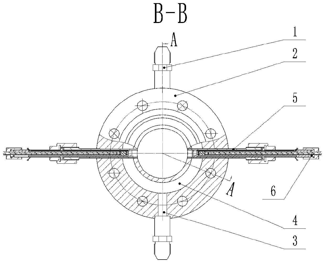
[0028] In this embodiment, the water-cooled concentrating optical fiber probe used in the stable section of a hypersonic low-density wind tunnel of the present invention is installed on a water-cooled test flange.

[0029] Such as image 3 As shown, the water-cooling test flange includes a water-cooling joint 1, a flange 2, a straight water channel 3, an annular water channel 4 and a test joint 5;

[0030] The flange 2 is a circular ring, and the cavity in the center of the circular ring is used to pass through the hypersonic low-density wind tunnel airflow. In the ring wall of the circular ring, an annular water channel 4 is arranged, and a uniform channel is opened on the annular water channel 4. Two straight waterways 3 perpendicular to the annular waterway 4 are arranged, and the straight waterway 3 is connected with a water-cooling joint 1, one water-cooling joint 1 is externally connected to the cooling water inlet pipe, and the other water-cooling joint 1 is externally ...


PUM


Abstract

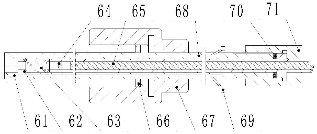
The invention discloses a water-cooled light-concentrating optical fiber probe used for a stable section of a hypersonic-speed low-density wind tunnel. Optical glass, a convex lens and an optical fiber are sequentially installed on the axis of the optical fiber probe from front to back, and sealing rings I are installed on both sides of the optical glass; a protective sleeve is installed outside the convex lens and the optical fiber in a sleeving mode, the front end of the protective sleeve closely abuts against the sealing ring I behind the optical glass, and a boss is arranged at the rear end of the protective sleeve; a shell sleeves the optical glass and the protective sleeve and is internally provided with a cooling water channel. The cooling water channel is connected with an externally-arranged cooling water system through a cooling water connector installed on the shell. The rear end of the shell and the boss at the rear end of the protective sleeve are connected by a connectingnut, and the rear end of the shell and the boss at the rear end of the protective sleeve are sealed by a seal ring III; and a step is arranged on the middle part of the shell, and a nut is installedat the step in a sleeving mode. The optical fiber probe is simple in structure and high in reliability, and can lead light generated by high-temperature and high-pressure gas in the stable section ofthe hypersonic-speed low-density wind tunnel to an optical measuring instrument.

Description

technical field [0001] The invention belongs to the technical field of hypersonic wind tunnel tests, and in particular relates to a water-cooled concentrating optical fiber probe used in a stable section of a hypersonic low-density wind tunnel. Background technique [0002] In hypersonic wind tunnels, especially high-temperature and high-pressure wind tunnel equipment such as hypersonic low-density wind tunnels and arc wind tunnels, the gas in the stable section is high-temperature and high-pressure gas. When measuring the emission spectrum or absorption spectrum of the gas in the stable section, it is necessary Install a dedicated fiber optic probe. The existing fiber optic probe does not have a cooling device, which makes the fiber probe easy to burn out, and has no light-gathering ability, which leads to low light collection efficiency of the fiber probe, which cannot meet the measurement requirements. At present, it is urgent to develop a special for hypersonic low-densi...

Claims


Application Information

Patent Timeline
IPC IPC(8): G01M9/06
CPCG01M9/06
Inventor 陈爱国严松李志辉李震乾龙正义王杰
Owner 中国空气动力研究与发展中心超高速空气动力研究所
Learn More