Matching structure of bridge girder erection machine supporting legs and main beam

A technology for matching structures and erecting machines, which is applied in erecting/assembling bridges, bridges, bridge construction, etc. It can solve problems such as high failure rate, difficult maintenance, complex structure, etc., and achieve low failure rate, convenient maintenance, and simple setting structure Effect

Pending Publication Date: 2020-01-21
HEFEI ZHENGHAO MECHANICAL TECH
View PDF1 Cites 0 Cited by
  • Summary
  • Abstract
  • Description
  • Claims
  • Application Information

AI Technical Summary

Problems solved by technology

[0006] The purpose of the present invention is to solve the problem that the variable-span longitudinal movement of the existing bridge erecting machine is realized by rolling on the track driven by the motor (hydraulic motor), reducer and rack and pinion drive; the displacement position is fixed, and the displacement to the corresponding position requires Manual positioning with positioning pins; the displacement position is fixed in size. When the bridge pier distance is not at the corresponding displacement position of the bridge erecting machine due to construction errors, it needs to be adjusted repeatedly; the technical problems of complex structure, high failure rate and difficult maintenance provide a kind of The matching structure between the outrigger and the main girder of the bridge erecting machine drives the multifunctional endless chain through the traction wheel of the bridge erecting machine, and the outrigger roller under the cover is dragged to roll on the track through the shackle connected on one side, so that When erecting the longitudinal variable span of the bridge, the main girder of the bridge erecting machine needs to be aligned with the bridge and pier to be erected, and the main girder is moved to a suitable position without manually inserting and pulling out the positioning pins, thereby improving the efficiency of the staff erecting the bridge; through The hoist installed on the upper side of the guide beam realizes the lifting of the guide beam. The operation of the guide beam is made more stable through the retractable auxiliary ejector rod and auxiliary oblique rod, thereby improving the stability of the bridge erecting machine; The jacking cylinder installed on the side enables the gantry outriggers to bear the load at both ends of the main beam when moving longitudinally, thereby reducing the damage of the fastening bolts on the main beam. The jacking cylinder has a simple structure, low failure rate and convenient maintenance; The hydraulic cylinder installed at the lower end of the hinge shaft makes it more stable when the hinge shaft drags the T-beam. The hydraulic cylinder is easy to operate and improves the efficiency of bridge erection; the steel wire rope is pulled by the motor to stretch and tighten the wire rope, thereby realizing beam transportation. The vertical movement of the slab, the bridge erecting machine equipment is easy to debug, and can meet the construction error of the bridge pier distance; through the winch seat and the connecting pillar set on one side of the hinge shaft, the hinge shaft and the main girder are buffered during the longitudinal movement, thereby improving the frame. The safety of the bridge machine in use reduces the cost of the bridge machine

Method used


Image

  • Matching structure of bridge girder erection machine supporting legs and main beam
  • Matching structure of bridge girder erection machine supporting legs and main beam
  • Matching structure of bridge girder erection machine supporting legs and main beam

Examples


Embodiment Construction

[0034] The technical solutions of the present invention will be clearly and completely described below in conjunction with the embodiments. Apparently, the described embodiments are only some of the embodiments of the present invention, not all of them. Based on the embodiments of the present invention, all other embodiments obtained by persons of ordinary skill in the art without creative efforts fall within the protection scope of the present invention.

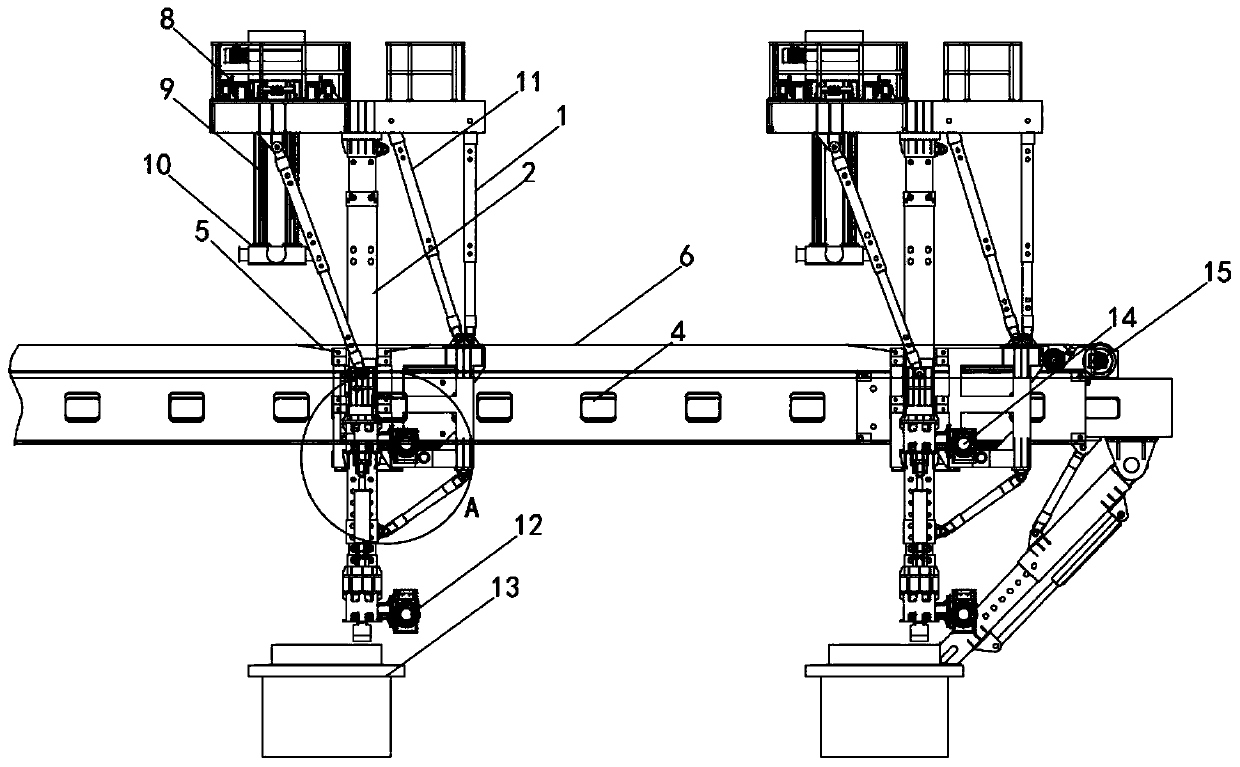
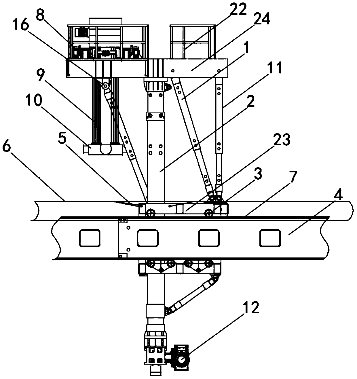
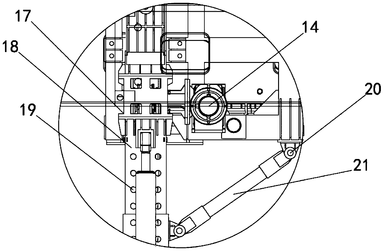
[0035] see Figure 1-3 As shown, a matching structure of a bridge erecting machine leg and a main girder, including a main girder 4, a gantry leg 2 and an endless chain 6;

[0036] One side of the main girder 4 is vertically provided with the gantry outrigger 2, and the upper and lower sides of the main girder 4 are symmetrically provided with a track 7, and a cover plate 23 is arranged above the track 7, and the cover plate 23 is perpendicular to the gantry outrigger 2, and the cover plate 23 is connected with the gantry ...


PUM


Abstract

The invention discloses a matching structure of bridge girder erection machine supporting legs and a main beam. Gantry supporting legs are perpendicularly arranged on one side of the main beam, railsare symmetrically arranged on the upper side and the lower side of the main beam, cover plates are arranged above the rails, the cover plates are perpendicular to the gantry supporting legs, the coverplates and the gantry supporting legs are fixedly connected, through traction wheels of a bridge girder erection machine, a multifunctional circular chain is driven, through a shackle connected on one side, supporting leg rollers below the cover plates are dragged to roll on the rails, therefore, when a variable span exists in the longitudinal direction of bridge erecting, the main beam of the bridge girder erection machine is aligned with a bridge required to be erected and piers, the main beam is moved to the suitable position, manual inserting and pulling of positioning pins are not needed, and the efficiency of bridge erecting by a worker is improved. Through a winch on the upper side of a guide beam, lifting of the guide beam is achieved, through telescopic auxiliary ejecting rods and auxiliary inclined rods, operation of the guide beam is more stable, and the stability of the bridge girder erection machine can be improved.

Description

technical field [0001] The invention relates to a matching structure, in particular to a matching structure of a bridge erecting machine leg and a main girder, and belongs to the technical field of bridge erection applications. Background technique [0002] The bridge erecting machine is the equipment that places the prefabricated girders on the prefabricated bridge piers. Bridge erecting machines fall into the category of cranes because their main function is to lift beams, transport them into position and then lower them down. But it is very different from the crane in the general sense. The conditions required are harsh, and there is beam walking, or longitudinal movement. [0003] The comparative document CN110184945A discloses a four-front outrigger for a bridge erecting machine and its erection method. The bridge erecting machine includes a main girder and a front outrigger crossbeam, and the front outrigger crossbeam is arranged on the main beam and can Longitudina...

Claims


Application Information

Patent Timeline
IPC IPC(8): E01D21/00E01D21/06
CPCE01D21/00E01D21/06
Inventor 郑之松
Owner HEFEI ZHENGHAO MECHANICAL TECH
Why Eureka
Try Eureka