A pair-roll mixing device and design method for emulsified ammonium oil explosives
A technology of mixing device and ammonium explosive, which is applied to explosives processing equipment, explosives, attack equipment and other directions, can solve the problems of easy to produce dead ends, insufficient mixing uniformity, segregation and other problems when mixing materials.
- Summary
- Abstract
- Description
- Claims
- Application Information
AI Technical Summary
Problems solved by technology
Method used
Image
Examples
Embodiment 1
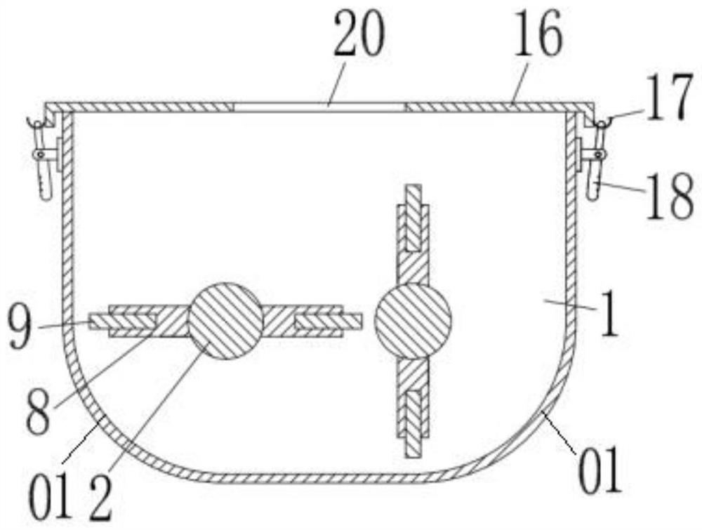
[0066] like Figure 1-3 As shown, a kind of emulsified ammonium oil explosive pair-roll mixing device of the present invention comprises a mixing tank, two spiral conveying rollers installed in parallel in the longitudinal direction in the mixing tank, and the spiral conveying rollers include a roller shaft and a Bracket vertically fixed on the roller shaft, the mixing tank is provided with a material inlet and a material outlet, and any one of the two spiral conveying rollers is equipped with a mixing driver and drives the other. The transmission part of the roller shaft. The roller shaft is provided with a plurality of brackets. The plurality of brackets on the roller shaft form several groups of brackets. Each bracket of each group of brackets is arranged along the axis of the roller shaft Arranged in a straight line at intervals, each group of brackets is arranged in a circular array along the centerline of the roller shaft; each bracket of any group of brackets on the sam...
Embodiment 2
[0071] A pair of roller mixing device for emulsified ammonium oil explosives of the present invention comprises a mixing tank, two screw conveying rollers arranged in the length direction of the mixing tank, the mixing tank is provided with a feed inlet and a discharge port, Any one of the plurality of rollers is equipped with a mixing driver and a transmission member for driving other rollers to mix materials, and a plurality of brackets are arranged on the rollers.
[0072] In this embodiment, the mixing driver is connected with a governor, and the governor may be a mechanical gearbox mechanically connected to the mixing driver, or a frequency converter electrically connected to the mixing driver. Changing the rotation speed of the roller shaft can change the rate of mixing and conveying and discharging.
[0073] The distance between the blade of the transverse spiral conveying roller and the inner wall of the mixing tank is 6mm.
[0074] like figure 1 , figure 2 As show...
Embodiment 3
[0077] The differences between this embodiment and embodiment 2 are:
[0078] The distance between the blades of the transverse spiral conveying roller and the inner wall of the mixing tank is 3.5 mm. Also in the mixing process, the porous granular structure of ammonium nitrate will not be destroyed, which ensures the product quality of the emulsified ammonium oil explosive. image 3 In the process, the bottom of the mixing tank and the two sides are excessively connected by chamfers (or called mixing tank chamfers), and the size of the mixing tank chamfers ensures that the blades of the transverse spiral conveyor roller and the inner wall of the mixing tank The distance is 3.5mm.
[0079] A board is provided on one side of the outlet. The outlet can be opened or closed through the plugboard. When the mixing drive is turned on for mixing, the outlet should be sealed by the plugboard first, and the mixing tank filled with materials will run for 3 minutes to 10 minutes before o...
PUM
| Property | Measurement | Unit |
|---|---|---|
| drag | aaaaa | aaaaa |
| yield strength | aaaaa | aaaaa |
| drag coefficient | aaaaa | aaaaa |
Abstract
Description
Claims
Application Information
 - R&D
- Intellectual Property
- Life Sciences
- Materials
- Tech Scout
- Unparalleled Data Quality
- Higher Quality Content
- 60% Fewer Hallucinations
Browse by: Latest US Patents, China's latest patents, Technical Efficacy Thesaurus, Application Domain, Technology Topic, Popular Technical Reports.
© 2025 PatSnap. All rights reserved.Legal|Privacy policy|Modern Slavery Act Transparency Statement|Sitemap|About US| Contact US: help@patsnap.com


