A pathological slicer

A pathological sectioning and slicing technology, applied in metal processing and other directions, can solve the problem of inability to serially section pathological tissues.

Inactive Publication Date: 2021-05-11
程云
View PDF7 Cites 0 Cited by
  • Summary
  • Abstract
  • Description
  • Claims
  • Application Information

AI Technical Summary

Problems solved by technology

[0003] In view of this, the present invention provides a pathological slicing device to solve the problem that the tissue slicing device in the prior art cannot continuously slice pathological tissues; the present invention can perform continuous and uniform slicing processing on pathological tissues, reducing the cost of pathological slicing time

Method used


Image

  • A pathological slicer
  • A pathological slicer
  • A pathological slicer

Examples


Embodiment 1

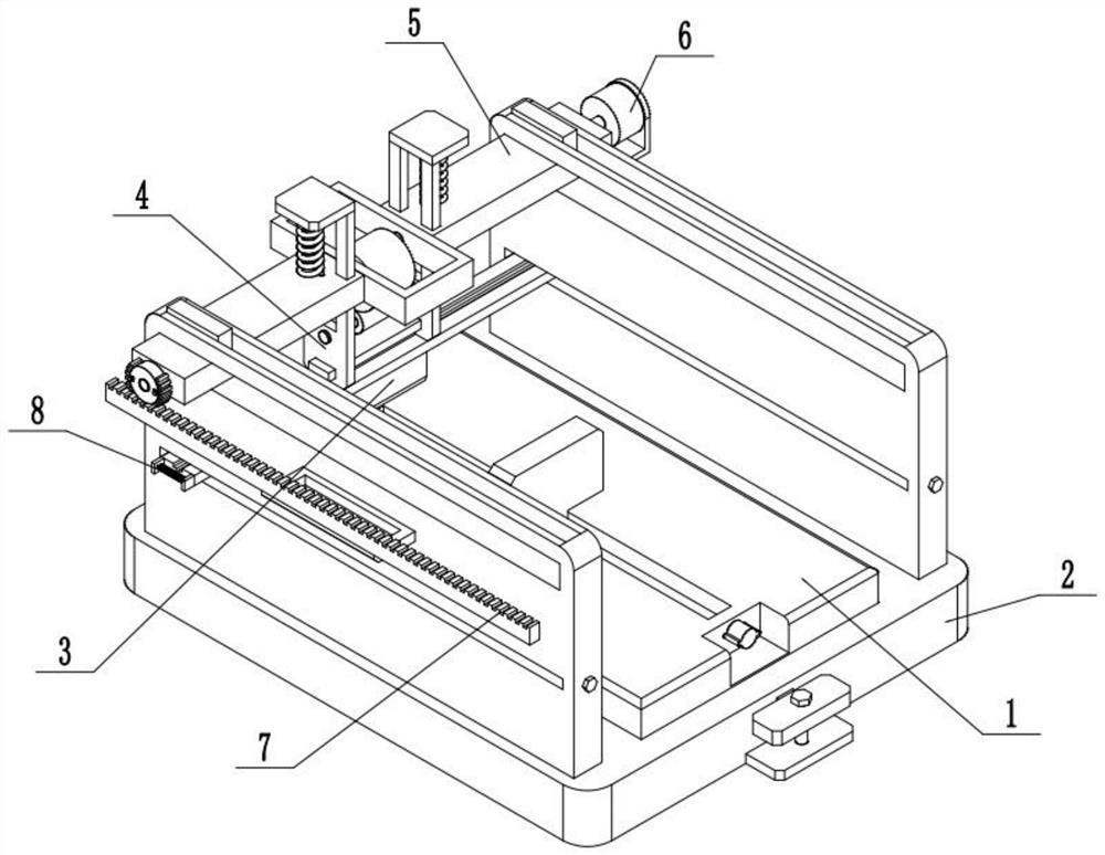
[0030] Such as Figure 1-10 As shown, a pathological slicing device includes a slicing platform 1, a complete machine support 2, a slice knife 3, a cutter seat 4, a sliding frame 5, a drive motor 6 and a straight rack 7, and the middle part of the complete machine support 2 is connected to There is a slicing platform 1; the slicing knife 3 is connected to the lower end of the cutter seat 4; the cutter seat 4 is connected to the sliding frame 5; the sliding frame 5 is slidably connected to the two ends of the whole machine support 2; the The drive motor 6 is connected to the sliding frame 5 through the motor seat; the drive motor 6 is connected to the cutter seat 4 in transmission; the cutter seat 4 is connected to the spur rack 7 in transmission; the spur rack 7 is fixedly connected to the frame of the whole machine 2 on.

[0031] A pathological slicing device of the present invention, when cutting a pathological tissue sample, after the pathological tissue sample is installe...

Embodiment 2

[0033] Such as Figure 1-10 As shown, the whole machine support 2 includes a base 201 and a side plate 202; two ends of the top surface of the base 201 are respectively fixedly connected to a side plate 202; the slicing platform 1 is connected to the base 201; the sliding frame 5 Slidingly connected to two side panels 202 .

Embodiment 3

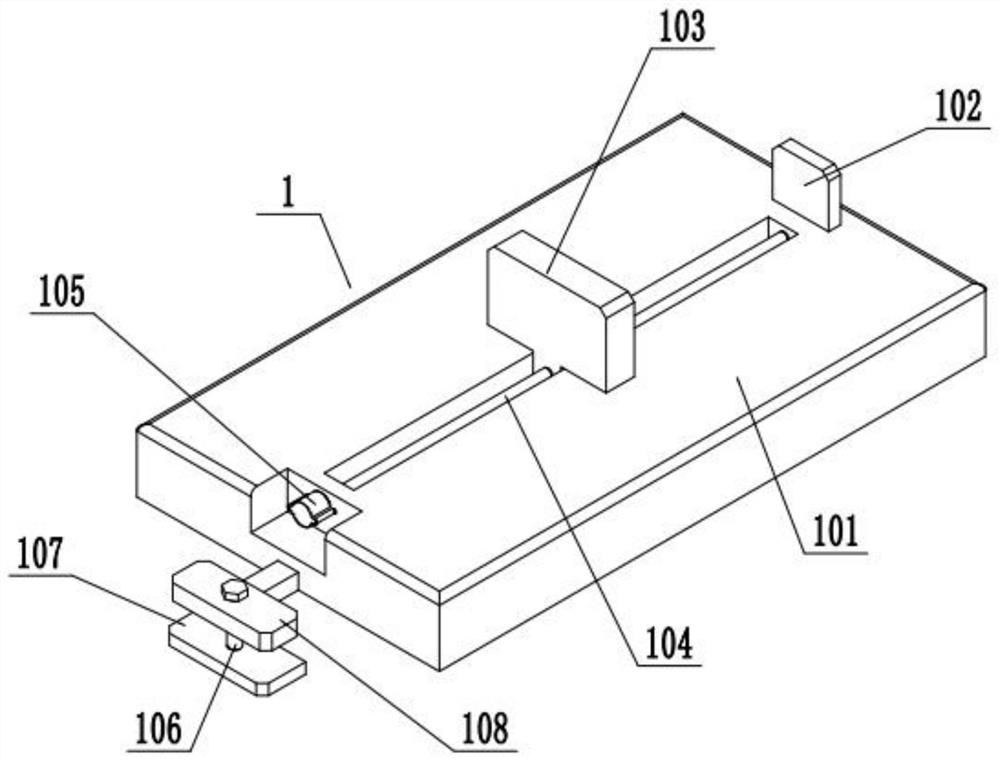
[0035] Such as Figure 1-10As shown, the slicing platform 1 includes a platform body 101, a fixed splint 102, a movable splint 103, a first screw 104, an adjustment rotary block 105, a second screw 106, a fixed plate 107 and a movable plate 108; the platform body 101 slides fit in the rectangular groove in the middle of the base 201; the fixed splint 102 is fixed on the front end of the top surface of the platform body 101; Connected to the first screw rod 104; the two ends of the first screw rod 104 are respectively rotated and matched with the two ends of the chute in the middle of the platform body 101; the rear end of the first screw rod 104 is fixedly connected to the adjusting block 105; The upper end of two screw rods 106 is threadedly connected on the movable plate 108; the rear end of the movable plate 108 is fixedly connected to the platform body 101; the lower end of the second screw rod 106 is rotatably fitted on the fixed plate 107; on the base 201. The slicing ...


PUM


Abstract

The present invention relates to the field of pathological slicers, in particular to a pathological slicer, comprising a slicing platform, a complete machine bracket, a slicer, a cutter seat, a sliding frame, a drive motor and a spur rack, the middle part of the complete machine bracket is connected to There is a slicing platform; the slicing knife is connected to the lower end of the cutter seat; the cutter seat is connected to the sliding frame; the sliding frame is slidably connected to both ends of the whole machine support; the driving motor is connected to the on the sliding frame; the driving motor is connected to the cutter seat; the cutter seat is connected to the spur rack; the spur rack is fixedly connected to the frame of the whole machine. The invention provides a pathological slicing device to solve the problem that the tissue slicing device in the prior art cannot continuously slice pathological tissues; the invention can perform continuous and uniform slicing processing on pathological tissues, reducing the time spent on pathological slicing.

Description

technical field [0001] The invention relates to the field of pathological slicers, in particular to a pathological slicer. Background technique [0002] In the pathology department, it is often necessary to remember the pathological section to judge the condition. Pathological section refers to taking a certain size of lesion tissue and making pathological section with histopathological method (usually the lesion tissue is embedded in paraffin block and cut into slices with a microtome. Thin slices, then stained with hematoxylin-eosin (H-E)], further examination of the lesion with a microscope, the occurrence and development of the lesion, and finally a pathological diagnosis. When performing pathological tissue sectioning, it may be necessary to slice the tissue continuously and uniformly. Traditional Tissue slicing devices often need to fix the cut tissue in a good position, and then use a single blade to cut slices one by one, which cannot perform continuous and uniform s...

Claims


Application Information

Patent Timeline
Patent Type & Authority Patents(China)
IPC IPC(8): B26D1/06B26D5/16B26D7/08B26D7/26
CPCB26D1/06B26D5/16B26D7/088B26D7/2614
Inventor 程云彭景贤谢虹
Owner 程云
Why Eureka
Try Eureka