
Zero-crossing detection circuit, zero-crossing detection method and switching power supply circuit

A zero-crossing detection circuit and zero-crossing detection technology, applied in the direction of measuring current/voltage, measuring electrical variables, high-efficiency power electronics conversion, etc., can solve the problem of abnormal zero-crossing detection function, unable to detect whether the inductor current is zero-crossing, zero-crossing Detect problems such as weak anti-interference ability

Pending Publication Date: 2020-01-17
HANGZHOU SILAN MICROELECTRONICS
View PDF0 Cites 7 Cited by
  • Summary
  • Abstract
  • Description
  • Claims
  • Application Information

AI Technical Summary

Problems solved by technology

[0004] The problem with the above-mentioned traditional solution is that if the sensitivity of zero-crossing detection is set high, when the output voltage across the load capacitor is high, the change range of the inductor current is relatively large, causing the signal to be detected to be prone to glitches. When the sensitivity of zero-crossing detection is high, the glitch on the signal will cause the output signal of the zero-crossing comparator to flip by mistake, making the zero-crossing detection result wrong, and it is easy to trigger the overvoltage protection, that is, the zero-crossing detection The anti-interference ability is weak; if the sensitivity of zero-crossing detection is set low, the output signal of the zero-crossing comparator will be reversed when the difference between the signal to be detected and the zero-crossing reference value is large, but when the load capacitance When the output voltage at both ends is very low, the change range of the inductor current is small, and it is difficult to produce a large difference between the signal to be detected and the zero-crossing reference value, so it may not be possible to detect whether the inductor current is zero-crossing, that is, the zero-crossing detection function abnormal

Method used


Image

  • Zero-crossing detection circuit, zero-crossing detection method and switching power supply circuit
  • Zero-crossing detection circuit, zero-crossing detection method and switching power supply circuit
  • Zero-crossing detection circuit, zero-crossing detection method and switching power supply circuit

Examples


Embodiment Construction

[0066] Various embodiments of the invention will be described in more detail below with reference to the accompanying drawings. In the various drawings, the same elements are denoted by the same or similar reference numerals. For the sake of clarity, various parts in the drawings have not been drawn to scale.

[0067] The invention can be embodied in various forms, some examples of which are described below.

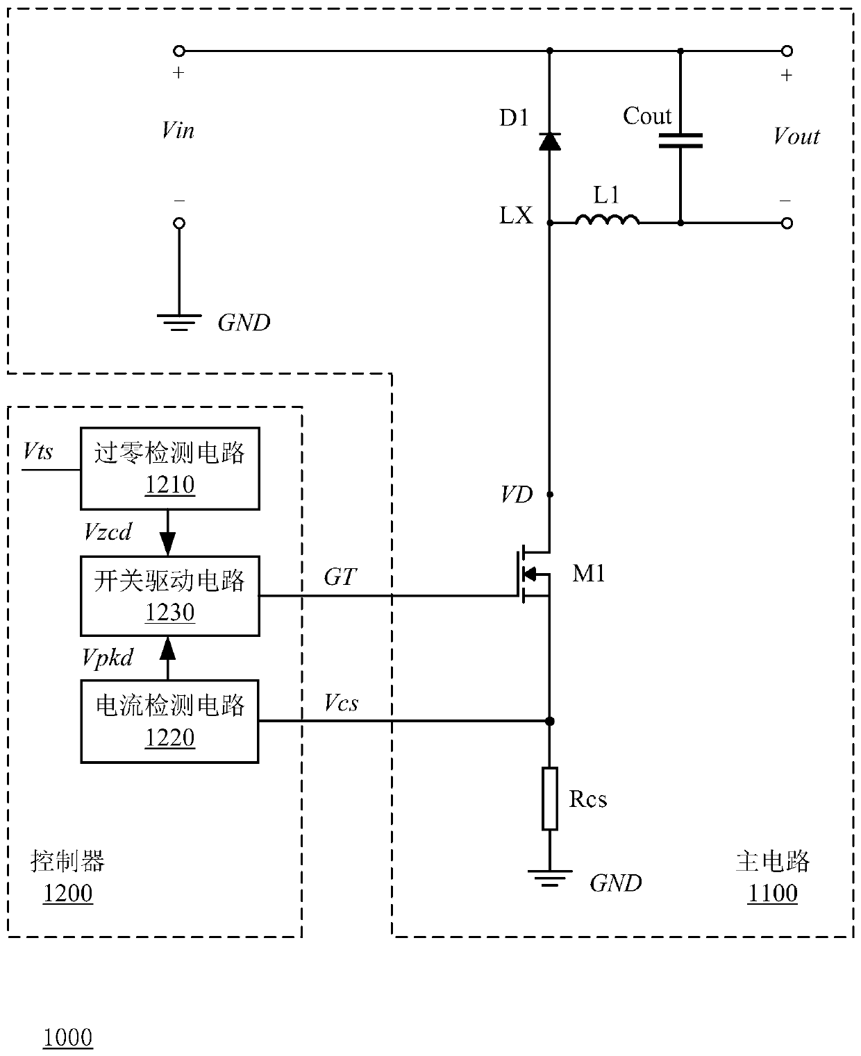
[0068] figure 1 A schematic circuit diagram of a switching power supply circuit according to the first embodiment of the present invention is shown.

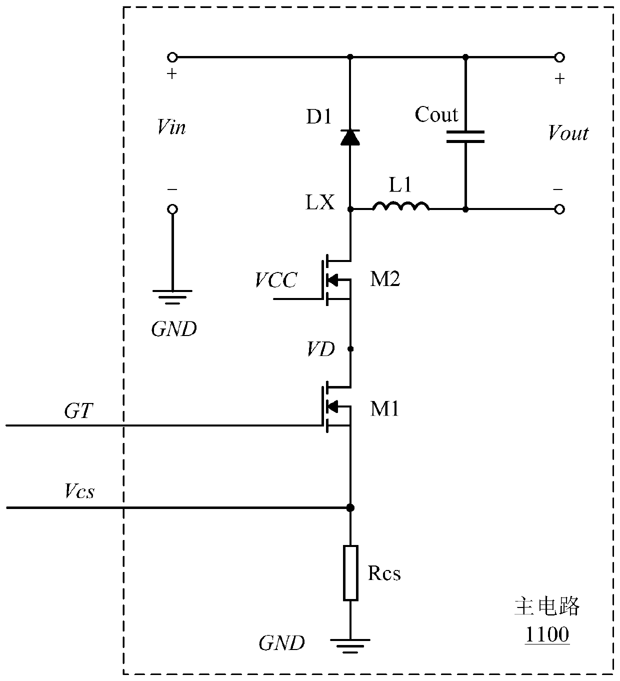
[0069] Such as figure 1 As shown, the switching power supply circuit 1000 includes a main circuit 1100 and a controller 1200 . The switching power supply circuit 1000 of this embodiment will be described below by taking a step-down structure as an example. However, the embodiments of the present invention are not limited thereto, and the basic concept of the present invention is also applicable to switching power supp...


PUM


Abstract

The invention discloses a zero-crossing detection circuit, a zero-crossing detection method and a switching power supply circuit. The zero-crossing detection circuit is used for providing a zero-crossing indication signal according to a to-be-detected signal. The to-be-detected signal responds to inductive current provided by the inductor; the inductor is charged when the power switch tube is switched on and discharged when the power switch tube is switched off so as to realize follow current, and the zero-crossing detection circuit comprises a detection unit for judging whether the current ofthe inductor is reduced to zero or not according to a zero-crossing reference value and the to-be-detected signal and providing a zero-crossing indication signal for representing a judgment result; and an adjusting signal generating unit which is used for detecting the follow current time of the inductor and adjusting the zero-crossing reference value according to the follow current time. The zero-crossing detection function can be optimized under the condition that the output voltages of the switching power supply circuit are different so as to prevent abnormities such as interference and detection failures.

Description

technical field [0001] The invention relates to the technical field of electronic circuits, and more specifically, to a zero-crossing detection circuit, a zero-crossing detection method and a switching power supply circuit. Background technique [0002] In some circuits, the characteristics of inductance to hinder current changes are often used to achieve some functions. For example, in a switching power supply circuit, the inductor can be charged during the conduction phase of the power drive tube to make the current flowing through the inductor reach the peak value, and the inductor can be used to discharge the load capacitor during the off phase of the power drive tube, so that the load capacitor at both ends The output voltage can be maintained within the allowable range. Therefore, by detecting whether the current flowing through the inductor is zero-crossing during the turn-off phase of the power drive tube, the output voltage at both ends of the load capacitor and th...

Claims


Application Information

Patent Timeline
Patent Type & Authority Applications(China)
IPC IPC(8): H02M3/156H02M1/44G01R19/175
CPCG01R19/175H02M1/44H02M3/1563H02M1/0009H02M1/0058Y02B70/10
Inventor 姚云龙
Owner HANGZHOU SILAN MICROELECTRONICS
Learn More