Boosted circuit and control method thereof

A technology of a boost circuit and a control method, which is applied in the field of circuits, can solve problems such as overvoltage breakdown of switching tubes, and achieve the effect of avoiding overvoltage breakdown

Active Publication Date: 2020-01-17
厦门科华数能科技有限公司
View PDF3 Cites 0 Cited by
  • Summary
  • Abstract
  • Description
  • Claims
  • Application Information

AI Technical Summary

Problems solved by technology

[0004] In view of this, the present invention provides a boost circuit and its control system to solve the problem of overvoltage breakdown of the switching tube in the existing boost circuit

Method used


Image

  • Boosted circuit and control method thereof
  • Boosted circuit and control method thereof
  • Boosted circuit and control method thereof

Examples


Embodiment Construction

[0035] In the following description, specific details such as specific system structures and technologies are presented for the purpose of illustration rather than limitation, so as to thoroughly understand the embodiments of the present invention. It will be apparent, however, to one skilled in the art that the invention may be practiced in other embodiments without these specific details. In other instances, detailed descriptions of well-known systems, devices, circuits, and methods are omitted so as not to obscure the description of the present invention with unnecessary detail.

[0036] In order to make the purpose, technical solution and advantages of the present invention clearer, specific embodiments will be described below in conjunction with the accompanying drawings.

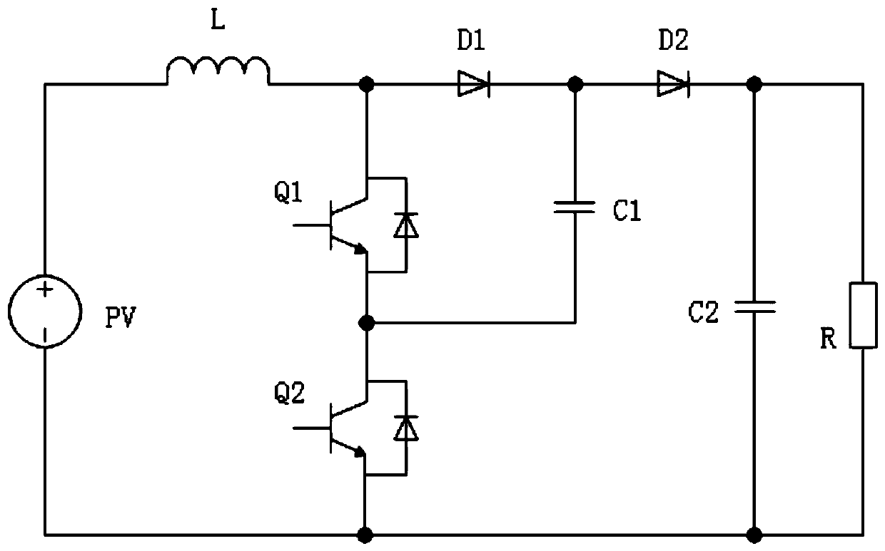
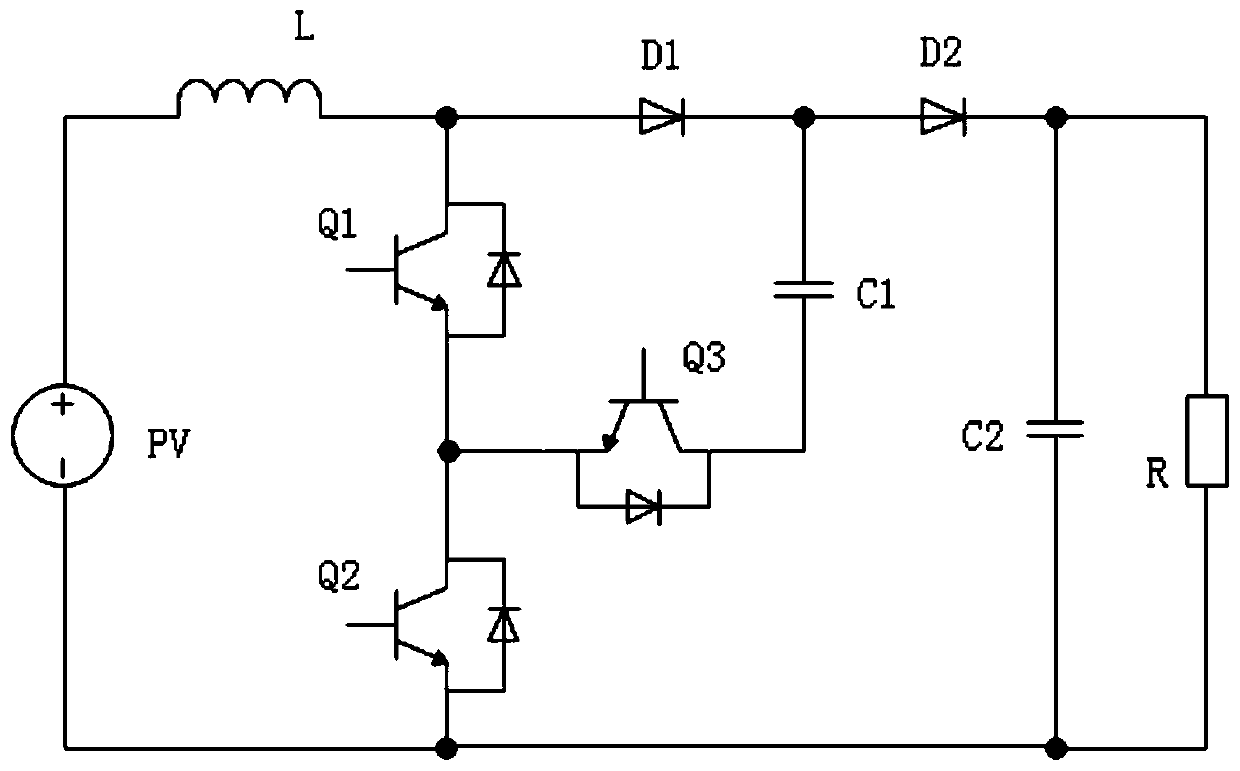
[0037] The first aspect of the embodiments of the present invention provides a boost circuit, such as figure 2 As shown, the boost circuit includes an input power supply PV, an inductor L, a first sw...


PUM


Abstract

The present invention provides a boosted circuit. In the boosted circuit, an input power supply, an inductor, a first switch tube and a second switch tube are sequentially connected in series to forma loop, the positive conduction end of a first one-way conduction device is connected between the inductor and the positive end of the first switch tube, and the negative end of a bus capacitor is connected to the negative end of the second switch tube; the positive end of a flying capacitor is connected between the reverse cut-off end of the first one-way conduction device and the positive conduction end of the second one-way conduction device, the negative end of the flying capacitor is connected to the positive end of the third switching tube, and the negative end of the third switching tube is connected between the negative end of the first switching tube and the positive end of the second switching tube; when the input power supply is initially powered on, the second switching tube and the third switching tube are both in an off state, so that the third switching tube can share the input voltage borne by the second switching tube, and the problem of overvoltage breakdown of the second switching tube can be avoided.

Description

technical field [0001] The invention belongs to the technical field of circuits, and in particular relates to a voltage boosting circuit and a control method thereof. Background technique [0002] A boost circuit (boost circuit) refers to a circuit that can convert an input voltage into a higher voltage for output to achieve power conversion. Generally, it is called a multi-level boost that can achieve an input greater than or equal to three levels. circuit. Under the same input conditions, the multi-level boost circuit can achieve a higher level of voltage output with a device of a smaller withstand voltage level by reducing the voltage stress of the power device. [0003] see figure 1 , is a three-level flying capacitor boost circuit in the prior art. When the input power supply PV of the circuit is initially powered on (assuming that the power-on voltage is Vin), since the voltage across the flying capacitor C1 is 0, Therefore, in the series circuit of inductor L, diod...

Claims


Application Information

Patent Timeline
Patent Type & Authority Applications(China)
IPC IPC(8): H02M1/32
CPCH02M1/32
Inventor 陈书生林加富陈新焕
Owner 厦门科华数能科技有限公司
Why Eureka
Try Eureka