A boost power conversion circuit and its control method

A technology for converting circuits and power, which is applied in the field of step-up power conversion circuits and its control, and can solve problems such as overvoltage breakdown of the switching tube Q2, and achieve the effect of avoiding overvoltage breakdown and realizing protection

Active Publication Date: 2022-04-08
SUNGROW POWER SUPPLY CO LTD
View PDF5 Cites 0 Cited by
  • Summary
  • Abstract
  • Description
  • Claims
  • Application Information

AI Technical Summary

Problems solved by technology

[0004] The present invention provides a boost power conversion circuit and its control method to solve the technical problem of overvoltage breakdown risk in the switching tube Q2 of the flying capacitor type boost power conversion circuit in the prior art

Method used


Image

  • A boost power conversion circuit and its control method
  • A boost power conversion circuit and its control method
  • A boost power conversion circuit and its control method

Examples


Embodiment Construction

[0054] The following will clearly and completely describe the technical solutions in the embodiments of the application with reference to the drawings in the embodiments of the application. Apparently, the described embodiments are only some of the embodiments of the application, not all of them. Based on the embodiments in this application, all other embodiments obtained by persons of ordinary skill in the art without creative efforts fall within the protection scope of this application.

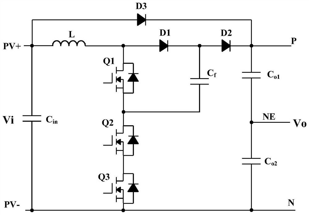
[0055] optional, see figure 2 , figure 2 It is a circuit topology diagram of a boost power conversion circuit provided by an embodiment of the present invention. The boost power conversion circuit provided by an embodiment of the present invention may include: an inductor L, a first diode D1, and a second diode D2 , the third diode D3, the first equalizing capacitor C o1 , the second equalizing capacitor C o2 , the first switch tube Q1, the second switch tube Q2, the flying capacitor C...


PUM


Abstract

The boost power conversion circuit and its control method provided by the present invention are applied in the technical field of power electronics. The circuit is connected in series in the branch circuit where the second switching tube is located to share the voltage equalizing module of the second switching tube. The pressure module is connected in series with the second switching tube to form a voltage equalizing branch. Under the first preset working condition where the voltage on the equalizing branch is greater than the rated withstand voltage of the second switching tube, each control terminal on the equalizing branch Receive the same control signal and work according to the control signal. Since each voltage equalizing module and the second switching tube on the voltage equalizing branch are controlled by the same control signal and have the same working state, no matter whether the second switching tube is in the normal working state or In the disconnected state, each voltage equalizing module can share the voltage applied to the second switching tube in the prior art, so as to protect the second switching tube and avoid overvoltage breakdown of the second switching tube.

Description

technical field [0001] The invention relates to the technical field of power electronics, in particular to a boost power conversion circuit and a control method thereof. Background technique [0002] The flying capacitor type step-up power conversion circuit is a circuit structure widely used in the field of power electronics technology. This circuit structure has the advantages of high working efficiency and frequency doubling of inductance, which can effectively reduce the weight and size of the inductance. It is beneficial to reduce the overall cost, weight and structural size of related devices using the circuit structure. [0003] see figure 1 , figure 1 It is a commonly used flying capacitor type three-level boost power conversion circuit in the prior art. figure 1 When the input terminal of the boost power conversion circuit shown is connected to the input voltage PV, the flying capacitor C f The capacitor voltage at both ends is zero, and the flying capacitor C ...

Claims


Application Information

Patent Timeline
Patent Type & Authority Patents(China)
IPC IPC(8): H02M3/158H02M1/32
CPCH02M3/158H02M1/32
Inventor 叶奇薛丽英陈长春
Owner SUNGROW POWER SUPPLY CO LTD
Why Eureka
Try Eureka