A method and system for improving the accuracy of cable fault measurement
A technology for measurement accuracy and cables, which is applied in the field of time domain reflection measurement cable faults, can solve problems such as large measurement errors, achieve the effects of reducing measurement errors, reducing blind zone distance, and improving measurement accuracy
- Summary
- Abstract
- Description
- Claims
- Application Information
AI Technical Summary
Problems solved by technology
Method used
Image
Examples
Embodiment 1
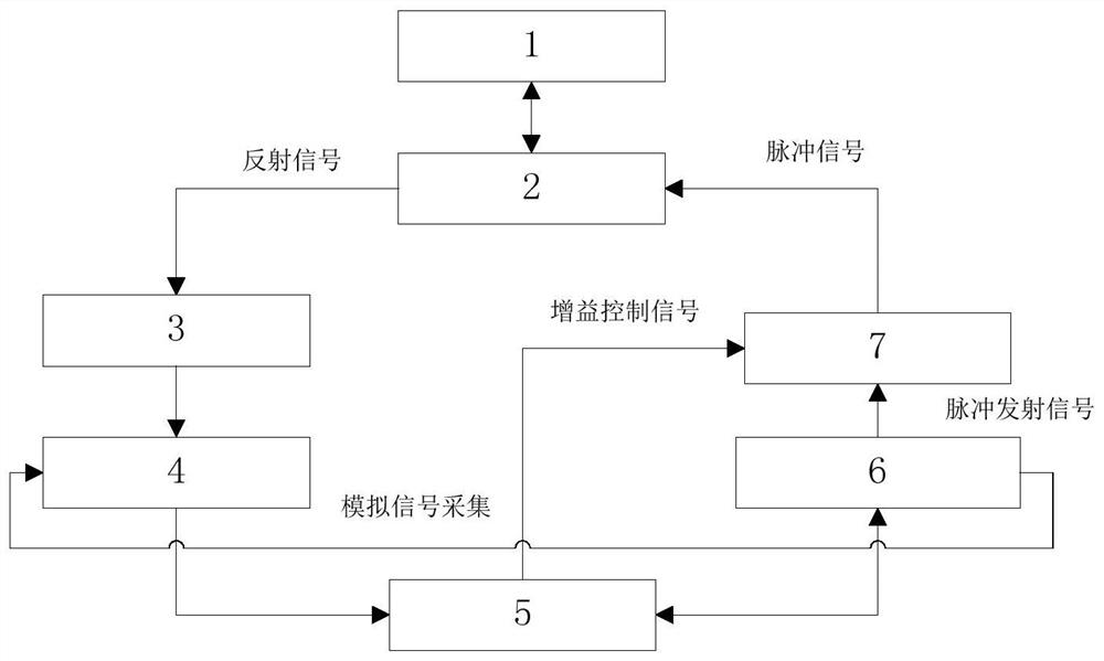
[0043] The embodiment of the present application discloses an electronic device for improving the accuracy of cable fault measurement, such as figure 1 shown, including:
[0044] Cable interface 1, impedance matching module 2, analog signal amplification module 3, ADC signal acquisition module 4, signal control and processing module 5, FPGA control module 6 and pulse control module 7;
[0045] The impedance matching module 2, the analog signal amplification module 3, the ADC signal acquisition module 4, the signal control and processing module 5, the FPGA control module 6 and the pulse control module 7 are sequentially connected;
[0046] The FPGA control module 6 is connected with the ADC signal acquisition module 4;
[0047] The cable interface 1 is connected to the impedance matching module 2;
[0048] The cable interface 1 is used to connect the cable under test;
[0049] The pulse control module 7 is used to send a pulse signal with increasing width to each section of ...
Embodiment 2
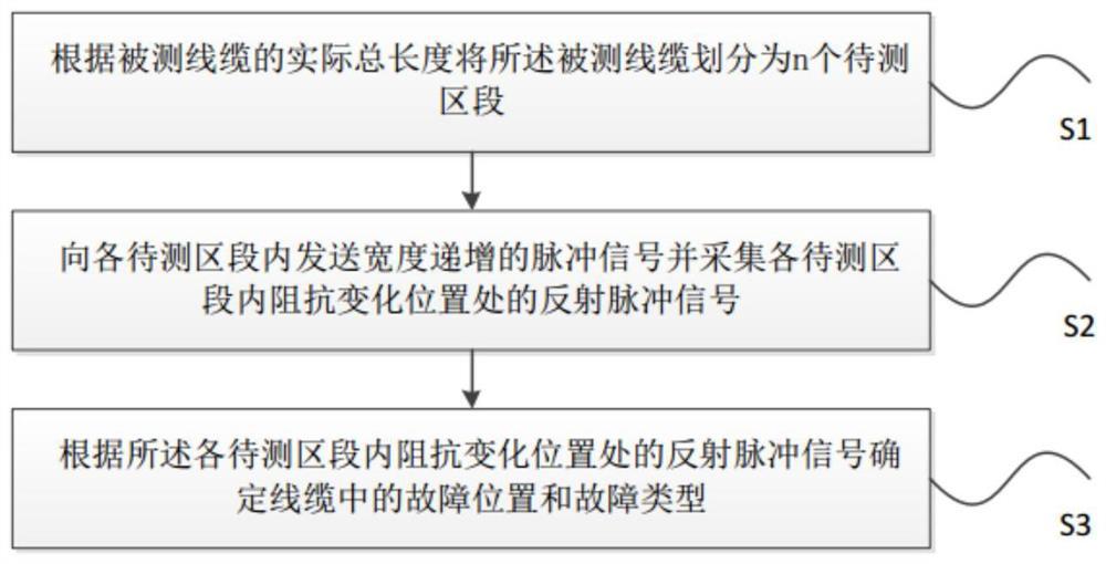
[0058] The embodiment of the present application discloses a method for improving the accuracy of cable fault measurement, such as figure 2 As shown, the method includes:
[0059] S1: divide the tested cable into n sections to be tested according to the actual total length of the tested cable;
[0060] Specifically, the section length of each section to be tested in the cable under test is determined according to the preset number of sections divided into sections to be tested by the cable under test and the actual total length of the cable under test. Or according to the actual total length of the cable under test, starting from one end of the cable under test, take a section shorter than the actual total length of the cable under test as the section to be tested, if the fault location is determined in the section to be tested and fault type, then end all operations. If the fault location and / or fault type are not determined in the section to be tested, start from the above...
Embodiment 3
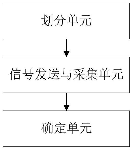
[0070] Based on the same idea of a method for improving the accuracy of cable fault measurement provided in Embodiment 2, this embodiment also provides a system for improving the accuracy of cable fault measurement, such as image 3 As shown, the system includes:
[0071] A division unit, configured to divide the tested cable into n sections to be tested according to the actual total length of the tested cable;
[0072] The signal sending and collecting unit is used to send a pulse signal with increasing width to each section to be tested and collect the reflected pulse signal at the impedance change position in each section to be tested;
[0073] The determination unit is configured to determine the fault location and fault type in the cable according to the reflected pulse signal at the impedance change position in each section to be tested.
[0074] The division unit is specifically used for:
[0075] Determine the section length l of the i-th section to be tested in th...
PUM
 Abstract
Description
Claims
Application Information
 - R&D Engineer
- R&D Manager
- IP Professional
- Industry Leading Data Capabilities
- Powerful AI technology
- Patent DNA Extraction
Browse by: Latest US Patents, China's latest patents, Technical Efficacy Thesaurus, Application Domain, Technology Topic, Popular Technical Reports.
© 2024 PatSnap. All rights reserved.Legal|Privacy policy|Modern Slavery Act Transparency Statement|Sitemap|About US| Contact US: help@patsnap.com


