Container type generating unit

A generator set, containerized technology, applied in the direction of engine components, machines/engines, mechanical equipment, etc., can solve the problems of increased cost, excessive size, large length, etc., to improve the utilization rate of packing space and prevent the phenomenon of hot air backflow , the effect of reducing the difficulty of layout

Active Publication Date: 2020-01-14
GUANGZHOU WANON ELECTRIC & MACHINE
View PDF8 Cites 3 Cited by
  • Summary
  • Abstract
  • Description
  • Claims
  • Application Information

AI Technical Summary

Problems solved by technology

[0002] For high-power generating sets driven by internal combustion engines, especially diesel engines, such a generating set is usually placed in a container like a container to achieve quietness and facilitate manufacturing, transportation, maintenance, maintenance, etc.; When using a larger power generator set, usually multiple generator sets are installed in the container to increase the overall output power; however, containerized generator sets with multiple generator sets in the prior art are usually arranged horizontally or vertically in the container. In order to meet the requirements of the overall power output of container generator sets, the horizontal arrangement will cause the width of the container to be too large, and in order to meet the width limit of road transport vehicles, the vertical arrangement is usually adopted. This arrangement causes the length to be too large, and the above-mentioned arrangement causes obstacles to the manufacture and transportation of the manufacturer, and is also not conducive to the miniaturization of the containerized generating set, and at the same time, this arrangement is also not conducive to the heat dissipation of the unit in the container;
[0003] And in order to avoid the size of the container being too large in one aspect of length or width, a larger number of single generator sets with slightly lower power should be installed in the container. The existing technical solutions can only be installed horizontally in the container body. Power units within 250kW, and an additional single generator will also increase the manufacturing cost of the manufacturer, increase the operation, maintenance, and maintenance costs of the user, and the arrangement of multiple low-power units also results in container space. Technical Issues with Low Utilization

Method used


Image

  • Container type generating unit
  • Container type generating unit
  • Container type generating unit

Examples


Embodiment Construction

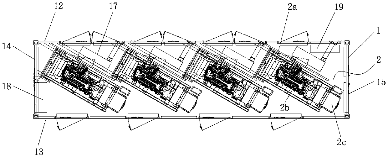
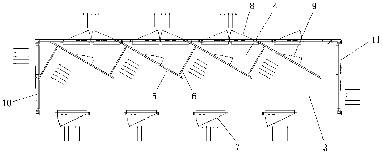
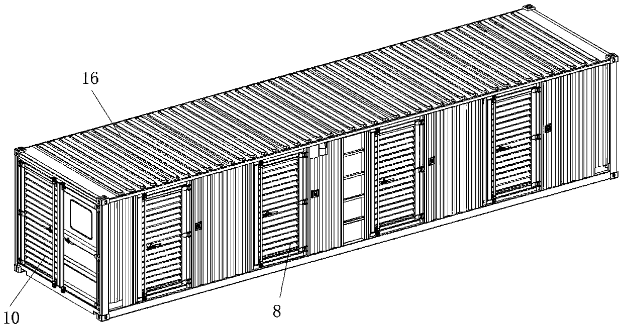
[0024] figure 1 It is a top view diagram of the internal structure of the present invention; figure 2 It is a top view diagram of the internal mechanism of the container of the present invention; image 3 Schematic for the three-dimensional structure of the present invention figure 1 ; Figure 4 Schematic for the three-dimensional structure of the present invention figure 2 .

[0025] As shown in the figure, the container-type generator set in this embodiment includes a container 1 and a plurality of generator sets 2 installed in the container, and the generator sets are installed obliquely and side by side in the container; The cuboid structure formed by the side wall 13, the left side wall 14, the right side wall 15, the top plate 16 and the bottom plate, in this embodiment, the front and rear directions are consistent with the container width, and the left and right directions are consistent with the container length direction, which will be described in detail below ...


PUM


Abstract

The invention discloses a container type generating unit. The container type generating unit comprises a container and multiple generating units mounted in the container, wherein the generating unitsare obliquely mounted in the container in parallel. According to the arrangement form, the width size of the container can be reduced, the length size of the container is taken into consideration, sothat on the premise that the container meets the limitation of road for the transport vehicle width, the power of single generating units arranged in the container is greatly increased, the selectionrange for single generating units for an internal combustion engine is larger, the arrangement difficulty is reduced, multiple high-power single generating units can be arranged in the container, thespace utilization rate of the container is increased, and manufacturing and transporting costs and operating, maintaining and serving costs are reduced.

Description

technical field [0001] The invention relates to the technical field of generators, in particular to a containerized generator set. Background technique [0002] For high-power generating sets driven by internal combustion engines, especially diesel engines, such a generating set is usually placed in a container like a container to achieve quietness and facilitate manufacturing, transportation, maintenance, maintenance, etc.; When using a larger power generator set, usually multiple generator sets are installed in the container to increase the overall output power; however, containerized generator sets with multiple generator sets in the prior art are usually arranged horizontally or vertically in the container. In order to meet the requirements of the overall power output of container generator sets, the horizontal arrangement will cause the width of the container to be too large, and in order to meet the width limit of road transport vehicles, the vertical arrangement is us...

Claims


Application Information

Patent Timeline
IPC IPC(8): F02B63/04F02B77/11F02B77/13
CPCF02B63/044F02B63/047F02B77/11F02B77/13
Inventor 岳帅武薛占轩黄沃林
Owner GUANGZHOU WANON ELECTRIC & MACHINE
Why Eureka
Try Eureka