
Gasification furnace slag mouth brick structure

A technology of brick structure and slag mouth, which is applied in the gasification of granular/powder fuel, the manufacture of combustible gas, the petroleum industry, etc. The effect of improving airflow conditions, extending operating life, and prolonging service life

Pending Publication Date: 2020-01-14
JIANGSU SOPO CHEM +1
View PDF2 Cites 0 Cited by
  • Summary
  • Abstract
  • Description
  • Claims
  • Application Information

AI Technical Summary

Problems solved by technology

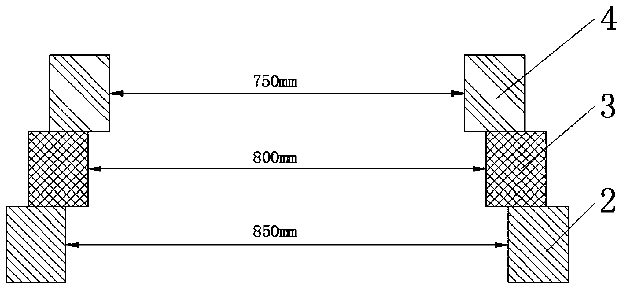
[0002] At present, most of the gasification furnace slag mouth brick structure is a three-layer dripping eaves structure (such as figure 2 As shown), when the synthetic gas flow passes through the three-layer slag brick, the diameter of the flow channel changes from 750mm to 800mm and then to 850mm; there are three steps in the three-layer brick, Chinese patent 201720523123.2, named as a coal-water slurry gasification furnace slag The drip eaves of the mouth brick discloses a coal-water slurry gasification furnace slag mouth brick with three drip eaves: drip eaves I, drip eaves II and drip eaves III; drip eaves I are located on the lower end surface of the upper brick in the slag mouth brick In the above, the dripping eaves I is a ring protruding downward from the lower end of the upper brick; the dripping eave II is located on the lower end of the middle brick of the slag mouth brick, and the dripping eave II is a ring protruding downward from the lower end of the middle brick; The dripping eaves III is located on the lower end face of the lower brick in the slag mouth brick. The dripping eaves III is a ring protruding downward from the lower end face of the lower bricks. However, the flow channel in this patent still has a stepped shape. Under high load operation, due to The velocity of the syngas increases, and when the high-speed airflow passes through the step surface, a vortex zone is formed, and the high-temperature syngas burns the refractory bricks repeatedly, causing the slag mouth to be burned, which directly affects the service life of the slag mouth brick and the safety of the gasifier; China Patent 201420641109.9, titled: A protective slag port structure of a pressurized coal-water slurry gasifier, discloses a slag port structure of a protective type coal-water slurry pressurized gasifier, the slag port structure includes a gasifier wall and a The inner side of the gasification furnace wall is a slag outlet made of multi-ring refractory bricks. The slag outlet is composed of an upper slag outlet and a lower slag outlet connected up and down. The lower part is in the shape of a funnel connected to the gasifier, the lower part of which is in the shape of a straight cylinder, and the lower part of the lower slag port is in the shape of a straight tube which is flush with the lower part of the upper slag port, and its bottom is supported by a brick support plate arranged under the gasifier wall. The inner edge of the bottom of the mouth protrudes from the edge of the brick support plate. In this patent, the upper part of the upper slag mouth is in the shape of a funnel connected with the conical bottom slope of the gasifier, and the lower part is in the shape of a straight cylinder. The lower part of the mouth is straight and flush, and under high-load operation, due to the increase in the velocity of the synthesis gas, when the high-speed air passes through the straight tube, it is easy to form a vortex zone;
[0003] At the same time, when the three-layer slag brick structure of the existing gasification furnace slag brick structure is combined, it lacks the treatment of the connection gap. The structure of the slag mouth brick is damaged and cracked. Therefore, the present invention proposes a structure of the slag mouth brick of the gasification furnace to solve the deficiencies in the prior art

Method used


Image

  • Gasification furnace slag mouth brick structure
  • Gasification furnace slag mouth brick structure

Examples


Embodiment Construction

[0015] In order to deepen the understanding of the present invention, the present invention will be further described below in conjunction with the examples, which are only used to explain the present invention, and do not constitute a limitation to the protection scope of the present invention.

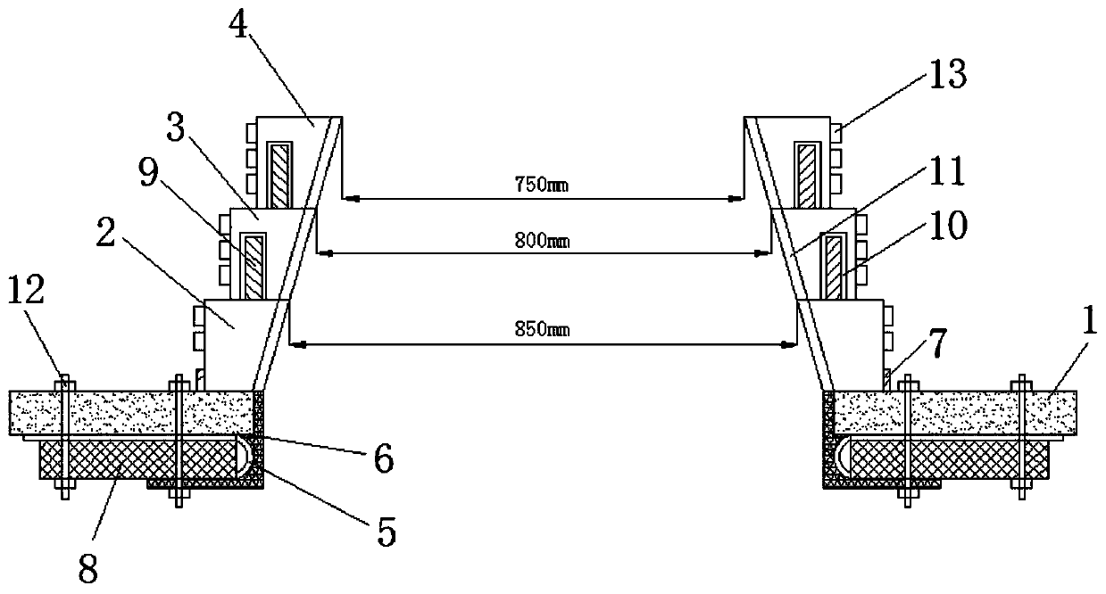
[0016] according to figure 1 As shown, this embodiment proposes a gasification furnace slag brick structure, including a brick support plate 1, a first slag brick 2, a second slag brick 3, a third slag brick 4, a chilling ring 5 and a tortoise shell net 6. The brick support plate 1 is provided with a brick groove 7, and the first slag mouth brick 2 is arranged inside the brick groove 7, and a second slag mouth is provided above the first slag mouth brick 2 through the first sealing assembly brick 3, the third slag brick 4 is provided above the second slag brick 3 through the second sealing assembly, one of the first slag brick 2, the second slag brick 3 and the third slag brick 4 T...


PUM


Abstract

The invention discloses a gasification furnace slag mouth brick structure, which comprises a brick supporting plate, a first slag mouth brick, a second slag mouth brick, a third slag mouth brick, a chilling ring and a hexsteel, wherein the second slag mouth brick is arranged above the first slag mouth brick through a first sealing assembly, the third slag mouth brick is arranged above the second slag mouth brick through a second sealing assembly, one side edges of the first slag mouth brick, the second slag mouth brick and the third slag mouth brick are inclined edge structures, a gasificationfurnace slag mouth brick runner formed by the inclined edge structures of the first slag mouth brick, the second slag mouth brick and the third slag mouth brick has a horn mouth shape, the chilling ring is arranged at one end of a fixing block, and the hexsteel is vertically arranged below the first slag mouth brick. According to the invention, the three-layer dripping eave structure of the existing gasification furnace slag mouth brick structure is changed into the horn mouth structure, and after the runner is changed into a horn mouth shape, the runner is gradually enlarged when high-speedsynthetic gas flow passes through a slag mouth, so that the gas flow state of the synthetic gas at the slag mouth is obviously improved, the forming of the vortex flow can be avoided, and the servicelife of the slag mouth brick can be prolonged.

Description

technical field [0001] The invention relates to the field of gasification furnaces, in particular to a slag mouth brick structure of a gasification furnace. Background technique [0002] At present, most of the gasification furnace slag mouth brick structure is a three-layer dripping eaves structure (such as figure 2 As shown), when the synthetic gas flow passes through the three-layer slag brick, the diameter of the flow channel changes from 750mm to 800mm and then to 850mm; there are three steps in the three-layer brick, Chinese patent 201720523123.2, named as a coal-water slurry gasification furnace slag The drip eaves of the mouth brick discloses a coal-water slurry gasification furnace slag mouth brick with three drip eaves: drip eaves I, drip eaves II and drip eaves III; drip eaves I are located on the lower end surface of the upper brick in the slag mouth brick In the above, the dripping eaves I is a ring protruding downward from the lower end of the upper brick; the...

Claims


Application Information

Patent Timeline
Patent Type & Authority Applications(China)
IPC IPC(8): C10J3/72C10J3/48
CPCC10J3/72C10J3/48
Inventor 朱桂生钟大捷邵守言谢泽宇许宝华邹菲刘玲唐丽
Owner JIANGSU SOPO CHEM
Learn More