
Automatic welding method and welding device of ship curved plate

A technology of automatic welding and curved panels, applied in welding equipment, arc welding equipment, manufacturing tools, etc., can solve the problems of carbon planing removal, deviation, welding bead offset, etc., to achieve the effect of improving performance and quality

Active Publication Date: 2020-01-14
GUANGZHOU SHIPYARD INTERNATIONAL LTD
View PDF6 Cites 4 Cited by
  • Summary
  • Abstract
  • Description
  • Claims
  • Application Information

AI Technical Summary

Problems solved by technology

According to the results of on-site flaw detection at these arc ignition and extinguishing positions, it was found that all the grounding arc ignition and extinguishing positions have welding defects, which must be removed by carbon planing after welding.
However, such as parameter adjustment, dry elongation control, and swing require manual judgment and independent processing, which vary from person to person, and there will be deviations in the judgment of details, which will ultimately affect the performance and quality of the weld
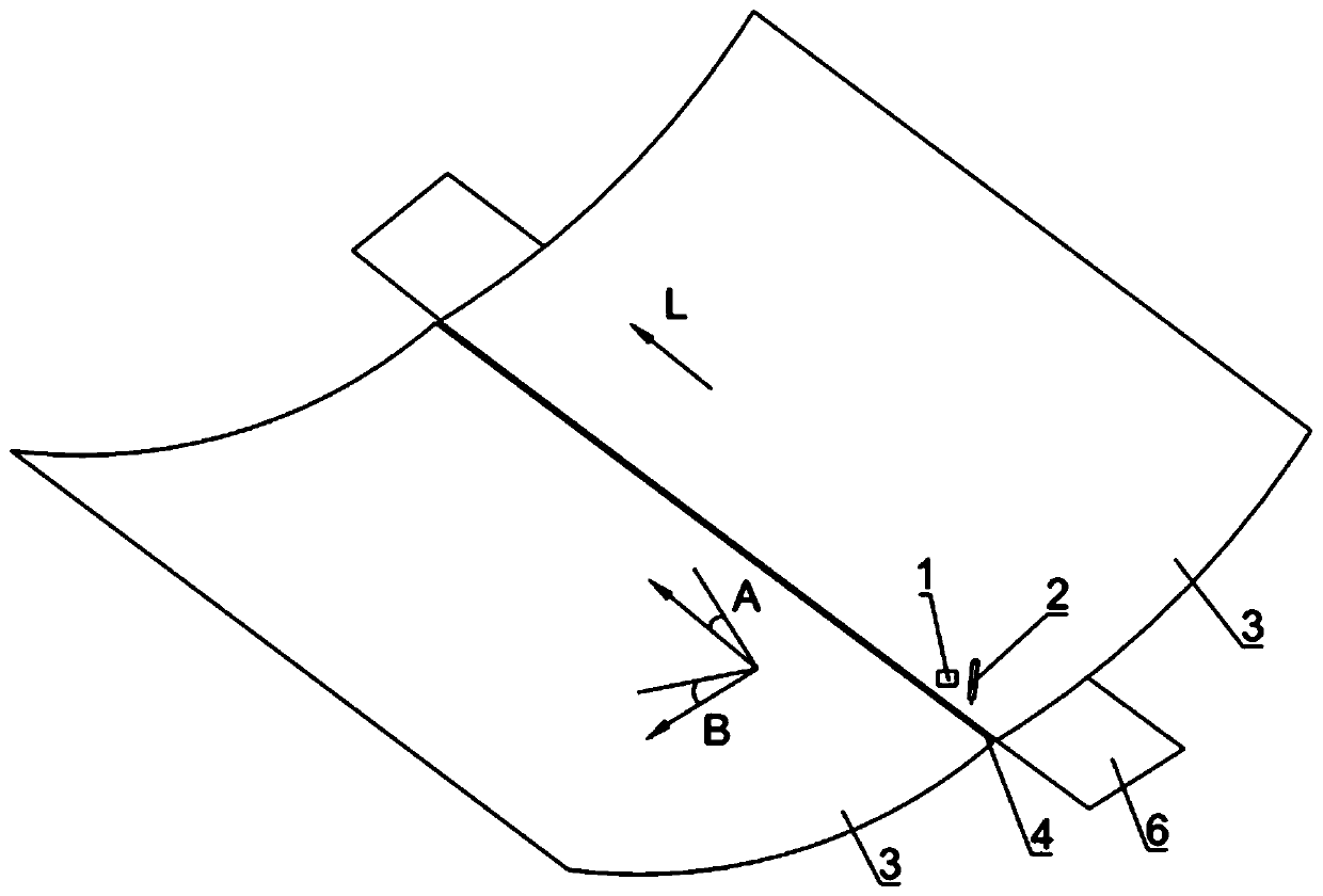
[0004] There are two types of rails for automatic welding of rails, one is rigid rails, but rigid rails do not conform to the welding of irregular curved panels
The other kind of track has certain flexibility, but because the track itself has a certain area, the stability is also poor, and it cannot completely fit the curved panel.
There is a deviation in the track, causing the weld bead to shift
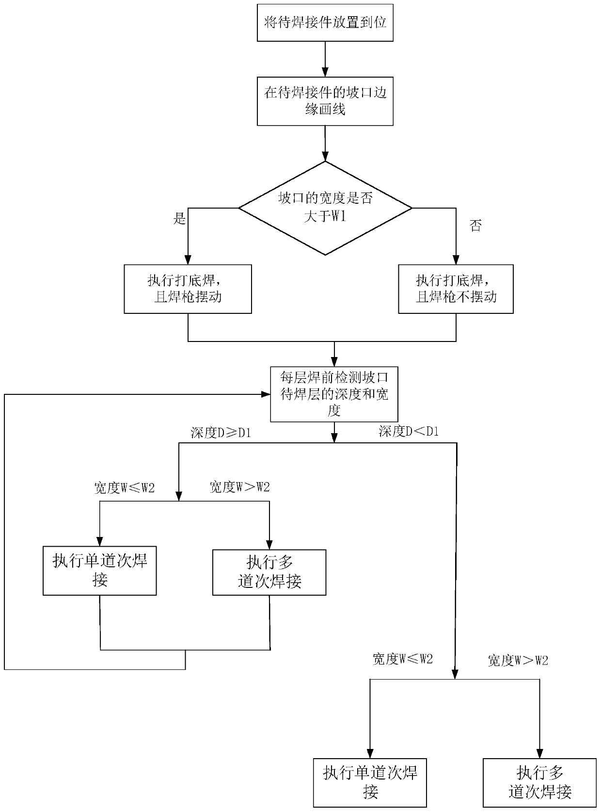
[0005] In addition, the current welding scheme adopts the method of detecting the groove before welding and then directly importing the whole set of procedures, and the welding of curved panels is prone to cumulative deviations

Method used


Image

  • Automatic welding method and welding device of ship curved plate
  • Automatic welding method and welding device of ship curved plate
  • Automatic welding method and welding device of ship curved plate

Examples


Embodiment Construction

[0040] The technical solutions of the present invention will be further described below in conjunction with the accompanying drawings and through specific implementation methods. It should be understood that the specific embodiments described here are only used to explain the present invention, but not to limit the present invention. In addition, it should be noted that, for the convenience of description, only the parts related to the present invention are shown in the drawings but not all of them.

[0041] Some orientation words are limited in the present invention, and under the situation of not making contrary description, the orientation words used are as " upper ", " lower ", " left ", " right ", " inner ", " outer " these orientation words It is adopted for easy understanding, and thus does not constitute a limitation to the protection scope of the present invention.

[0042] In the present invention, unless otherwise clearly specified and limited, a first feature bein...


PUM


Abstract

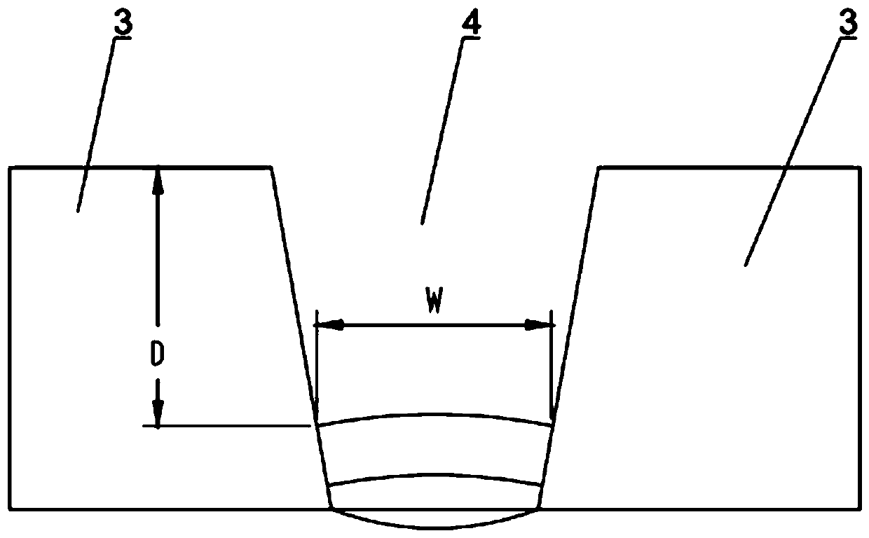
The invention relates to the technical field of ship manufacturing, and particularly discloses an automatic welding method and welding device of a ship curved plate. The automatic welding method of the ship curved plate comprises a welding execution procedure. The welding execution procedure comprises the following steps of executing backing weld; executing at least one of filling welding and cosmetic welding; in each welding procedure, at least carrying out one layer of welding, before executing of each layer of welding, through a visual tracking system, recognizing the depth of a layer to bewelded and the width of the layer to be welded of a groove, and according to the depth and the width, selecting welding process parameters; and enabling a welding gun mechanism to be electrically connected with the visual tracking system, and enabling the welding gun mechanism to adjust a motion track through the visual tracking system. Manual operation of the welding gun mechanism can be avoided, in the welding process, arc breaking is not needed, and the property and the quality of a welding seam are improved. According to the automatic welding method of the ship curved plate, the propertyand the quality of the welding seam can be improved, and welding way deviation and cumulative departure in the welding process can be avoided.

Description

technical field [0001] The invention relates to the technical field of shipbuilding, in particular to an automatic welding method and welding device for curved hull panels. Background technique [0002] At present, there are some curved plate structures in the shipbuilding industry and steel structure industry, such as the outer plates of the bow and stern areas of ships. Welder welding. [0003] The main problems of the semi-automatic welding method for hull curved panels are as follows: due to the line shape of the groove, the operation is difficult, and skilled workers are required to operate the welding torch. Due to personnel factors during the operation, the arc needs to be interrupted every 600mm or so. The operator moves and adjusts the arc before starting the arc. According to the on-site flaw detection results of these arc ignition and extinguishing positions, it was found that all the priming arc ignition and extinguishing positions had welding defects, which mu...

Claims


Application Information

Patent Timeline
IPC IPC(8): B23K9/127B23K9/12
CPCB23K9/1274B23K9/12
Inventor 吴磊磊马金军黎剑新刘宝辉
Owner GUANGZHOU SHIPYARD INTERNATIONAL LTD
Learn More