
Auxiliary electric toothbrush

An electric toothbrush and brush handle technology, applied in the field of oral care, can solve problems such as difficult to control strength and unsatisfactory cleaning effect, and achieve the effect of removing dental plaque

Pending Publication Date: 2020-01-14
SHENZHEN JOINTRONIC TECH CO LTD
View PDF0 Cites 2 Cited by
  • Summary
  • Abstract
  • Description
  • Claims
  • Application Information

AI Technical Summary

Problems solved by technology

[0003] The main purpose of the present invention is to propose an electric toothbrush for auxiliary use, which aims to solve the problem that existing conventional toothbrushes are difficult to control and have unsatisfactory cleaning effects when brushing teeth for others or pets, while existing finger-cot toothbrushes lack Technical Problems of Protecting Human Fingers

Method used


Image

  • Auxiliary electric toothbrush
  • Auxiliary electric toothbrush
  • Auxiliary electric toothbrush

Examples


Embodiment 1

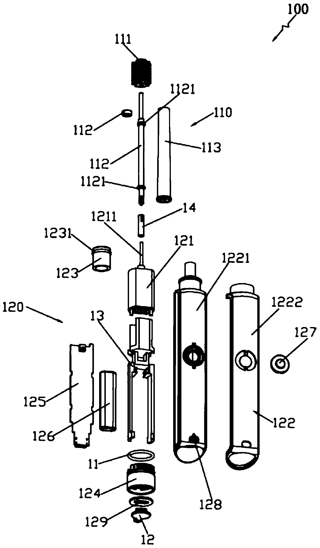
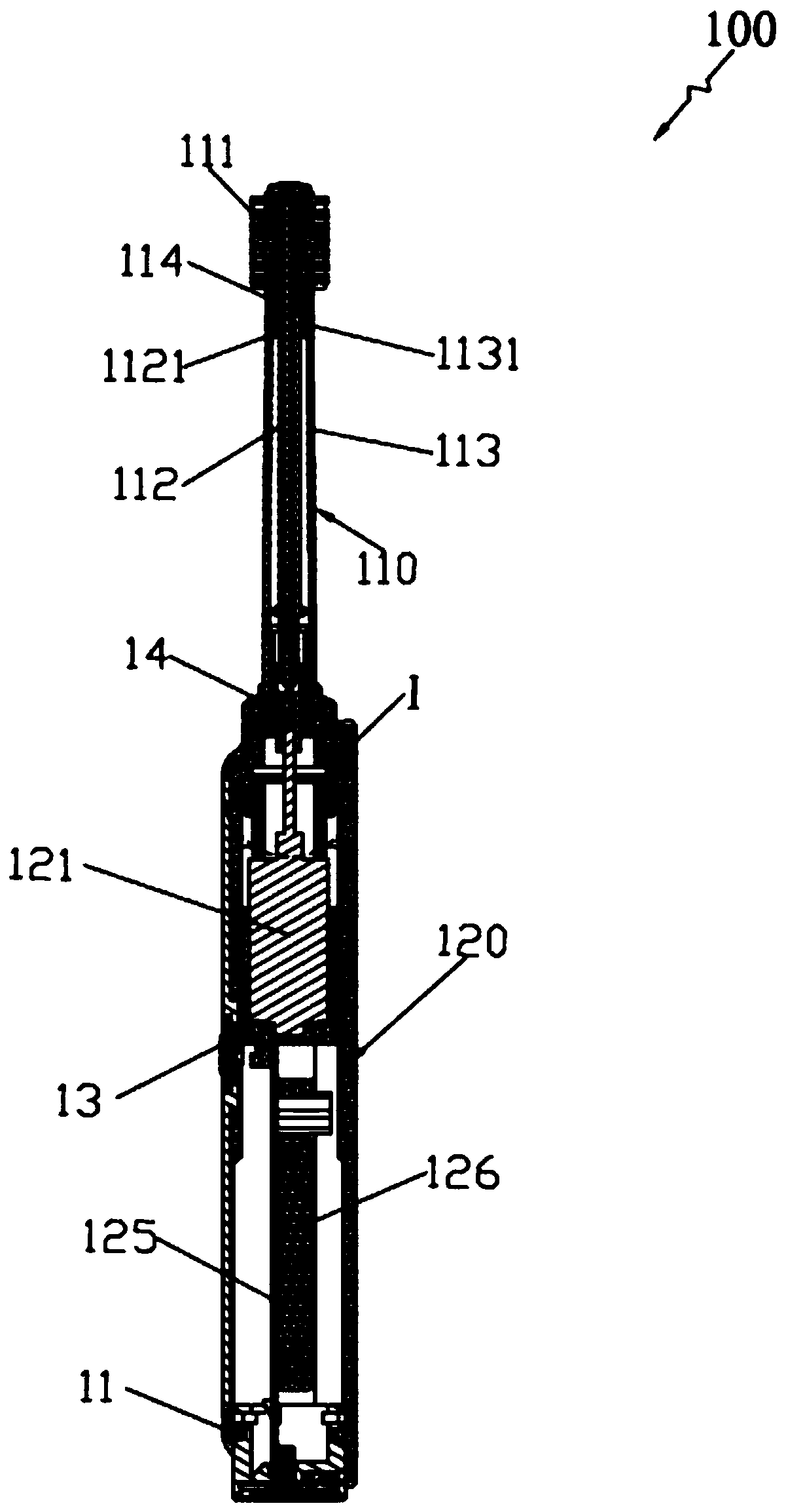
[0023] Such as figure 1 and figure 2 As shown, Embodiment 1 of the present invention provides an electric toothbrush 100 for auxiliary use. The electric toothbrush 100 includes a brush head 110 and a handle 120. The brush head 110 includes a brush head hair planting part 111, a transmission rod 112 and a brush head housing 113. The transmission rod 112 is built in the brush head housing 113, and the transmission rod 112 is rotated and matched with the brush head housing 113. One end of the transmission rod 112 protrudes outwards and extends to the outside of the brush head housing 113 to socket and fix the brush head hair planting parts 111, the brush handle 120 has a built-in drive motor 121, the brush head 110 is detachably connected to the top of the brush handle 120, and the drive motor 121 drives the end of the transmission rod 112 away from the brush head hair planting part 111, so that the brush head hair planting part 111 follows The transmission rod 112 rotates arou...

Embodiment 2

[0032] Embodiment 2 of the present invention provides an electric toothbrush for auxiliary use. The only difference between this electric toothbrush and the electric toothbrush 100 in Embodiment 1 is that Figure 5 As shown, the brush head 210 in this embodiment is a bent brush head, that is, the brush head housing 213 is a bent cylindrical structure, the transmission rod 212 includes a short rod body 2121 and a long rod body 2122, and the short rod body 2121 and the brush head housing 213 Carry out rotation fit, one end of the short rod body 2121 is socketed and fixed with the brush head hair planting part 211, the other end of the short rod body 2121 is socketed and fixed with the first bevel gear 2123, and the drive motor is connected to one end of the long rod body 21, and the other end of the long rod body 2122 One end is sleeved and fixed with a second bevel gear 2124, and the second bevel gear 2124 is meshed with the first bevel gear 2123, so that the long rod body 2122 ...


PUM


Abstract

The invention discloses an auxiliary electric toothbrush, and belongs to the technical field of oral care. The toothbrush comprises a brush head and a brush handle, the brush head comprises a brush head flocking part, a transmission rod and a brush head shell, the transmission rod is arranged in the brush head shell and rotatably matched with the brush head shell, one end of the transmission rod projects outwards, extends outside the brush head shell and is fixedly connected with the brush head flocking part in a sleeving manner, a driving motor is arranged in the brush handle, the brush headis detachably connected at the top end of the brush handle, and the driving motor is connected with one end, far away from the brush head flocking part, of the transmission rod in a driven manner, sothat the brush head flocking part rotates around the axis of the brush head shell along with the transmission rod. By the aid of the technical scheme, the toothbrush can effectively solve the technical problems that when teeth of other people or pets are brushed by an existing conventional toothbrush, the strength is difficultly controlled, cleaning effect is not ideal, and fingers of a user cannot be protected when an existing fingerstall type toothbrush is used.

Description

technical field [0001] The invention relates to the technical field of oral care, in particular to an auxiliary electric toothbrush. Background technique [0002] Nowadays, pet owners pay more and more attention to pet oral problems. Since pets cannot automatically brush their teeth, they must be assisted by the owner for oral cleaning. Similarly, as China gradually enters the elderly society, there are more and more elderly chronically ill patients. Many chronically ill patients cannot take care of themselves and need others to serve them. Their oral cleaning needs also require special tools. And the toothbrush on the market now mainly contains following several kinds: 1, the conventional toothbrush (comprising manual toothbrush or common electric toothbrush) that people use, it is easy to damage teeth when brushing teeth for long-term patients, the elderly, pets, because it is for others Or when pets brush their teeth, the strength is sometimes indiscriminate or difficult...

Claims


Application Information

Patent Timeline
IPC IPC(8): A01K13/00A61C17/22A61C17/26
CPCA01K13/001A61C17/26A61C17/225A61C17/222A61C17/221
Inventor 李孟阳邵羲晖王刚
Owner SHENZHEN JOINTRONIC TECH CO LTD
Learn More