
Time correlation redundancy removal method for temperature sensing data

A time-dependent, data-sensing technology, applied in other database retrieval, special data processing applications, etc., can solve the problems of increasing sensor computing energy consumption, data redundancy data, unresearched, etc., and achieve the effect of reducing transmission energy consumption

Active Publication Date: 2020-01-10
SOUTH CENTRAL UNIVERSITY FOR NATIONALITIES
View PDF5 Cites 0 Cited by
  • Summary
  • Abstract
  • Description
  • Claims
  • Application Information

AI Technical Summary

Problems solved by technology

In view of the following problems in the previous methods of removing redundancy, when removing data redundancy, only the data whose similarity distance is smaller than the threshold th is removed, but no study has been made on whether the limited non-redundant data can be passed after removing redundant data. The data presents the important information represented by the original data
At the same time, in the process of de-redundancy, there are still the following problems. When there are large data fluctuations, the consideration of local maximum and minimum values
For the situation where the data fluctuation range is particularly small, the data is stable, and the data will face a large number of situations smaller than the threshold th, which will cause the threshold failure problem, causing the data for a long period of time to be regarded as redundant data
Finally, when comparing data similarity, it will increase the computational energy consumption of the sensor

Method used

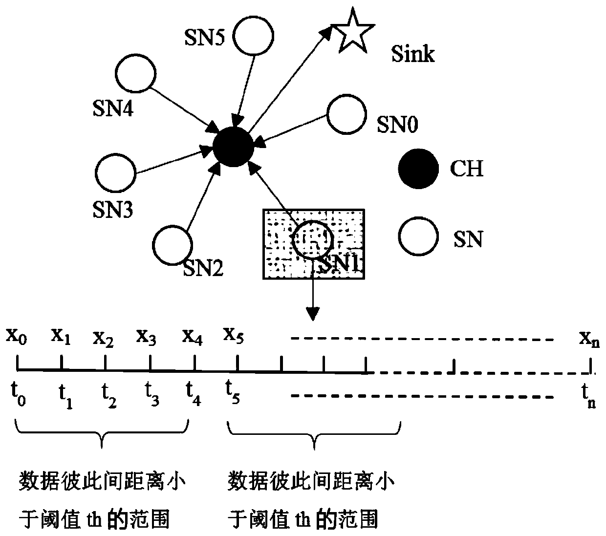
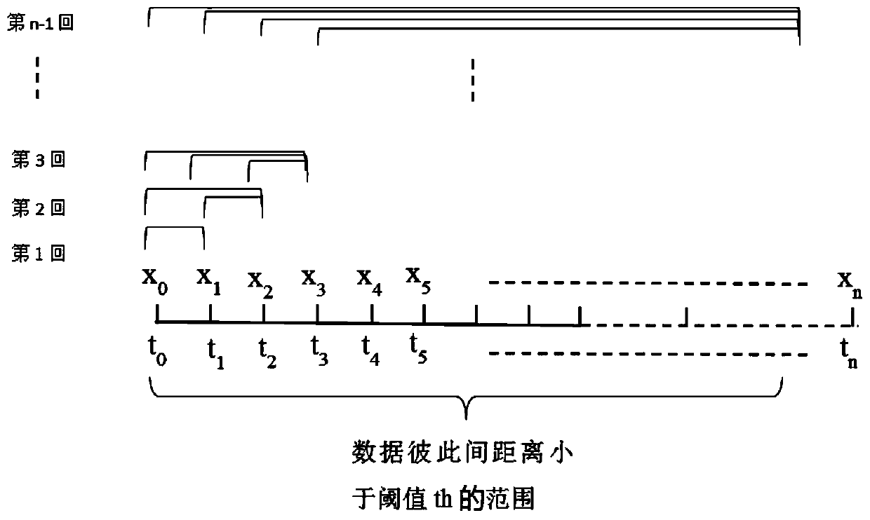
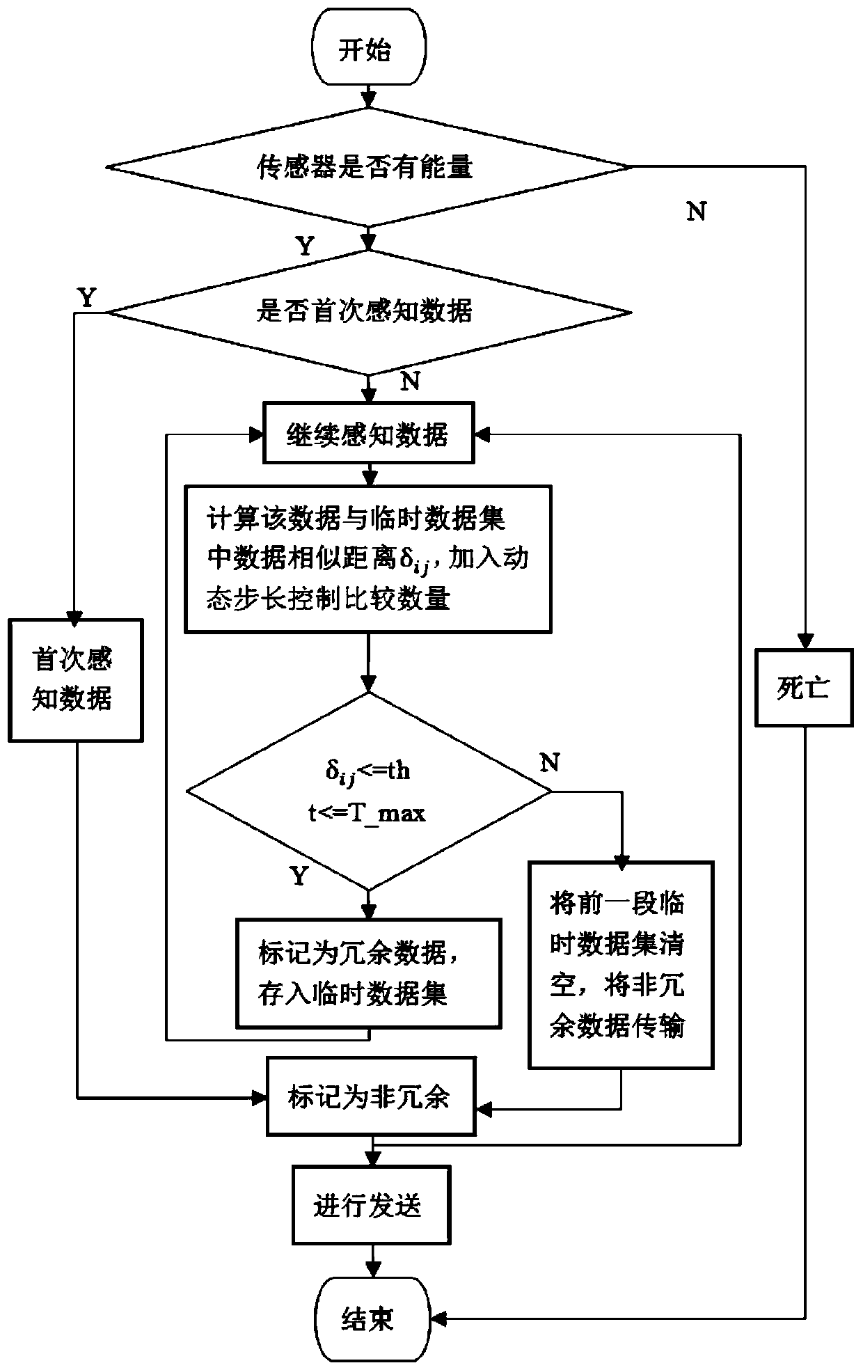

Image

  • Time correlation redundancy removal method for temperature sensing data
  • Time correlation redundancy removal method for temperature sensing data
  • Time correlation redundancy removal method for temperature sensing data

Examples


Embodiment Construction

[0061] In order to make the object, technical solution and advantages of the present invention clearer, the present invention will be further described in detail below in conjunction with the accompanying drawings and embodiments. It should be understood that the specific embodiments described here are only used to explain the present invention, not to limit the present invention.

[0062] The time correlation de-redundancy method for temperature sensing data according to the embodiment of the present invention, the method includes the following steps:

[0063] Step 1. Obtain the temperature sensing data collected by multiple temperature sensors, and perform preliminary processing on it, and construct a temperature sensing data de-redundancy model based on the time series correlation of dynamic change step size, and deal with the large amount of redundant information in the data process;

[0064] Step 2. Determine whether the temperature sensing data currently collected by th...


PUM


Abstract

The invention discloses a time correlation redundancy removal method for temperature sensing data, and the method comprises the steps of 1, obtaining the temperature sensing data collected by a plurality of temperature sensors, and carrying out the preliminary processing on the temperature sensing data; 2, calculating the similar distance between the currently acquired temperature sensing data andthe data in a temporary data set; 3, calculating the farthest time difference of the continuous redundant temperature sensing data in each period, setting a threshold value of the similar distance and a numerical value of maximum time control, comparing the similar distance with the threshold value of the similar distance, and comparing the farthest time difference with the numerical value of themaximum time control to serve as a redundant condition for judging redundancy; adding a dynamic step length to control the comparison quantity during calculation; and 4, outputting the temperature sensing data after time correlation redundancy removal. According to the method, the special data can be reserved, the problem of the excessive data loss caused by the excessive redundancy elimination is solved, and the temperature sensing data is more reasonable during the redundancy elimination process and more conforms to the acceptance form of a user.

Description

technical field [0001] The invention relates to the technical field of wireless sensor networks, in particular to a time-correlation de-redundancy method for temperature sensing data. Background technique [0002] With the advancement of social science and technology, wireless sensor networks are used in all aspects of life (such as: medical treatment, trajectory, earthquake, military, Internet of Things, agricultural and industrial pollution monitoring, etc.), providing people with a large amount of monitoring data all the time. Due to the limitations of the sensor network's own conditions, limited battery energy, memory, capacity and communication range, etc., limit the life of the network. The life of the network mainly depends on the battery energy, and the energy consumption is manifested in three aspects: node communication, data processing and data transmission. With the sharp increase of sensing data, a large amount of data transmission will be generated, which will...

Claims


Application Information

Patent Timeline
IPC IPC(8): G06F16/90
CPCG06F16/90
Inventor 朱容波李媛丽王俊王德军
Owner SOUTH CENTRAL UNIVERSITY FOR NATIONALITIES
Learn More