Powder conveying device for curing agent coating production

A powder conveying and curing agent technology, applied in the direction of feeding devices, chemical instruments and methods, chemical/physical processes, etc., can solve the problems of production reaction impact, agglomeration, etc., and achieve the effect of preventing agglomeration

Inactive Publication Date: 2020-01-10
湖北汉耐尔新材料科技有限公司
View PDF0 Cites 0 Cited by
  • Summary
  • Abstract
  • Description
  • Claims
  • Application Information

AI Technical Summary

Problems solved by technology

[0003] In the production process of curing agent coating, corresponding powder needs to be added, and the powder conveying device is used for feeding processing, but most of the traditional powder conveying devices have a relatively simple structure, and the powder is prone to agglomeration when stored in the storage mechanism , the traditional powder conveying device does not address this problem, and it is easy to have a certain impact on the subsequent production reaction

Method used


Image

  • Powder conveying device for curing agent coating production
  • Powder conveying device for curing agent coating production
  • Powder conveying device for curing agent coating production

Examples


Embodiment 1

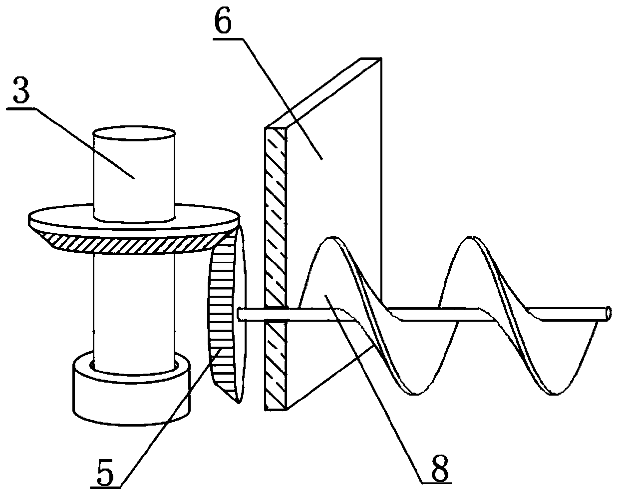
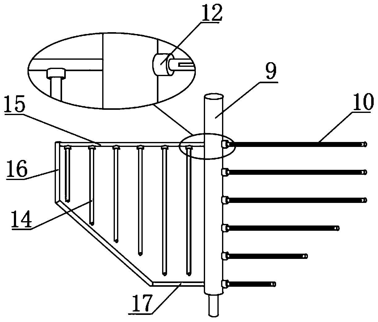
[0027] refer to Figure 1-3 , a powder delivery device for the production of curing agent coatings, including a storage tank 1 with legs welded at the four corners of the bottom. The shaft is connected with the drive rod 9 which is rotationally connected with the storage tank 1, the outer wall of one side of the drive rod 9 is provided with the first stirring rod 10 which is equidistant and horizontally distributed, and the outer wall of the side of the drive rod 9 is far away from the first stirring rod 10 Fixed rod 15 is welded, and the bottom outer wall of fixed rod 15 is provided with the second stirring rod 14 of equidistant vertical distribution, and the opposite side of first stirring rod 10 and drive rod 9 and the second stirring rod 14 and fixed rod 15 The opposite sides of each are welded with an arc-shaped connection block 12, the bottom end of the storage tank 1 is welded with a vertically arranged first delivery section 2, and the first delivery section 2 is welde...

Embodiment 2

[0035] refer to figure 1 and image 3 , a powder conveying device for the production of curing agent coatings. In order to prevent the powder from adhering to the inner wall of the storage tank 1 and causing subsequent inconvenient cleaning, this embodiment also includes a driving rod 9 close to the One side of the fixed rod 15 is welded with a horizontally arranged connecting rod 17, and the ends of the connecting rod 17 and the fixed rod 15 are welded with the same brush rod 16, and the brush rod 16 is adapted to the inner wall of the storage tank 1.

[0036] Working principle: When in use, use the setting of the brush rod 16 to brush the inner wall of the storage tank 1 through the brush rod 16 during the stirring, powder feeding and conveying process, thereby preventing the powder from adhering to the storage tank 1 inner wall.


PUM


Abstract

The invention discloses a powder conveying device for curing agent coating production, which comprises a material storage tank with legs welded at the four corners of the bottom, wherein a deceleration motor is fixedly arranged on the outer wall of the top of the material storage tank; an output shaft of the deceleration motor is connected with a driving rod rotationally connected with the material storage tank through a coupling; the outer wall of one side of the driving rod is provided with first stirring rods which are horizontally distributed at equal distances; and the outer wall of one side of the driving rod which is far away from the first stirring rod is welded with a fixing rod. The outer wall of the bottom of the fixed rod is provided with second stirring rods which are vertically distributed at equal distances, and arc-shaped connecting blocks are welded on the opposite sides of the first stirring rod and the driving rod and the opposite sides of the second stirring rod andthe fixed rod. According to the invention, through the horizontally arranged first stirring rods and the vertically arranged second stirring rods, powder in the storage tank can be uniformly stirredalong with the rotation of the deceleration motor, and the powder conveying device has the advantage of preventing agglomeration.

Description

technical field [0001] The invention relates to the technical field of curing agent paint production, in particular to a powder conveying device for curing agent paint production. Background technique [0002] Curing agent, also known as hardening agent, curing agent or stabilizer, is a kind of substance or mixture that promotes or controls the curing reaction. Resin curing is through chemical reactions such as condensation, ring closure, addition or catalysis, so that the thermosetting resin undergoes an irreversible change process, and curing is completed by adding a curing agent. Curing agent is an essential additive, whether it is used as adhesives, coatings, or castables, it is necessary to add a curing agent, otherwise the epoxy resin cannot be cured. [0003] In the production process of curing agent coating, corresponding powder needs to be added, and the powder conveying device is used for feeding processing, but most of the traditional powder conveying devices hav...

Claims


Application Information

Patent Timeline
Patent Type & Authority Applications(China)
IPC IPC(8): B01J4/00
CPCB01J4/007B01J2204/002
Inventor 汪绍平
Owner 湖北汉耐尔新材料科技有限公司
Why Eureka
Try Eureka