Light intensity-based electronic feedback manual zoom lens

An electronic feedback, zoom lens technology, used in optics, optical components, testing optical performance, etc., can solve the problem of difficult to ensure accurate information about adjusting the lens magnification to the exact position of the current magnification, incorrect reading of the lens magnification value, Low work efficiency and other problems, to achieve the effect of electronic information feedback, simple structure and convenient operation

Pending Publication Date: 2020-01-03
TZTEK TECH
View PDF0 Cites 0 Cited by
  • Summary
  • Abstract
  • Description
  • Claims
  • Application Information

AI Technical Summary

Problems solved by technology

[0002] In the prior art, when the manual continuous zoom lens is used in various measurement environments, most of them rely on manual visual reading of the magnification value of the current position of the lens indicated on the scale circle of the lens, and then the read current position of the lens Manually input the magnification value of the lens to the lower-level equipment (mostly PC) connected to the lens, but in this process, it is difficult to ensure accurate information on whether the lens is adjusted to the exact position of the current magnification when adjusting the magnification, and errors are prone to occur Read the situation of the magnification value of the lens, and every time the lens is adjusted, it is necessary to manually read the magnification value of the current position of the lens, and then manually input the read magnification value of the current position of the lens to the lower-level equipment connected to the lens, In this way, not only the operation is cumbersome, but also the working efficiency of the manual confirmation method is relatively low, and it is also prone to errors during manual input; in addition, this continuous zoom lens with magnification adjustment instructions includes a position detection signal emission and optical signal receiving unit, a position detection Signal reflectors, etc., to achieve electronic information feedback capabilities. The position detection signal reflector is used as an electronic feedback device, which reflects the detection signal from the position detection signal transmitting and optical signal receiving unit back to the position detection signal transmitting and optical signal receiving unit. , the position detection signal reflector is fixedly installed on the main body of the manual focus lens, and rotates synchronously with the manual focus lens main body, and the position detection signal reflector is provided with light reflectors arranged in a Gray code coding manner to mark positions. The light reflector is electrically connected to the position detection signal transmitter and optical signal receiver unit, provides power for the position detection signal transmitter and optical signal receiver unit, and decodes the signal from the position detection signal transmitter and optical signal receiver unit to the lower level connected to it equipment, but the electronic feedback system of the continuous zoom lens with magnification adjustment instructions needs more than three photoelectric receivers, and a certain number of holes need to be drilled on the lens barrel. The electronic feedback system is relatively complicated, and the design and production The cost is also higher

Method used


Image

  • Light intensity-based electronic feedback manual zoom lens
  • Light intensity-based electronic feedback manual zoom lens
  • Light intensity-based electronic feedback manual zoom lens

Examples


Embodiment Construction

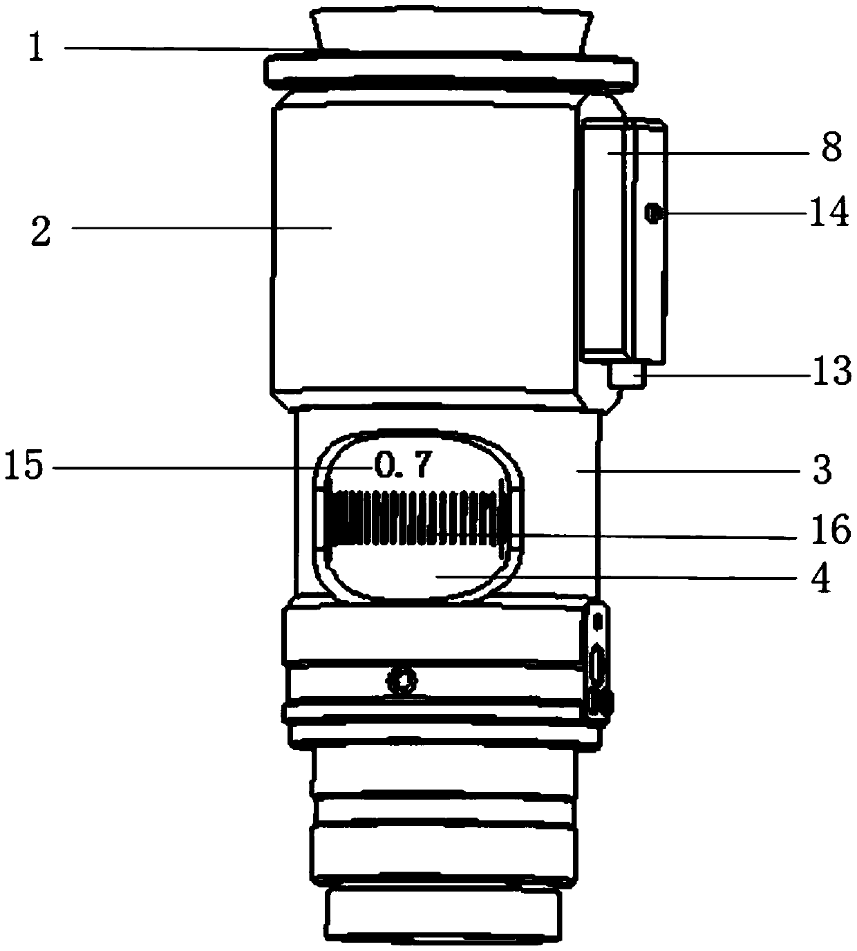
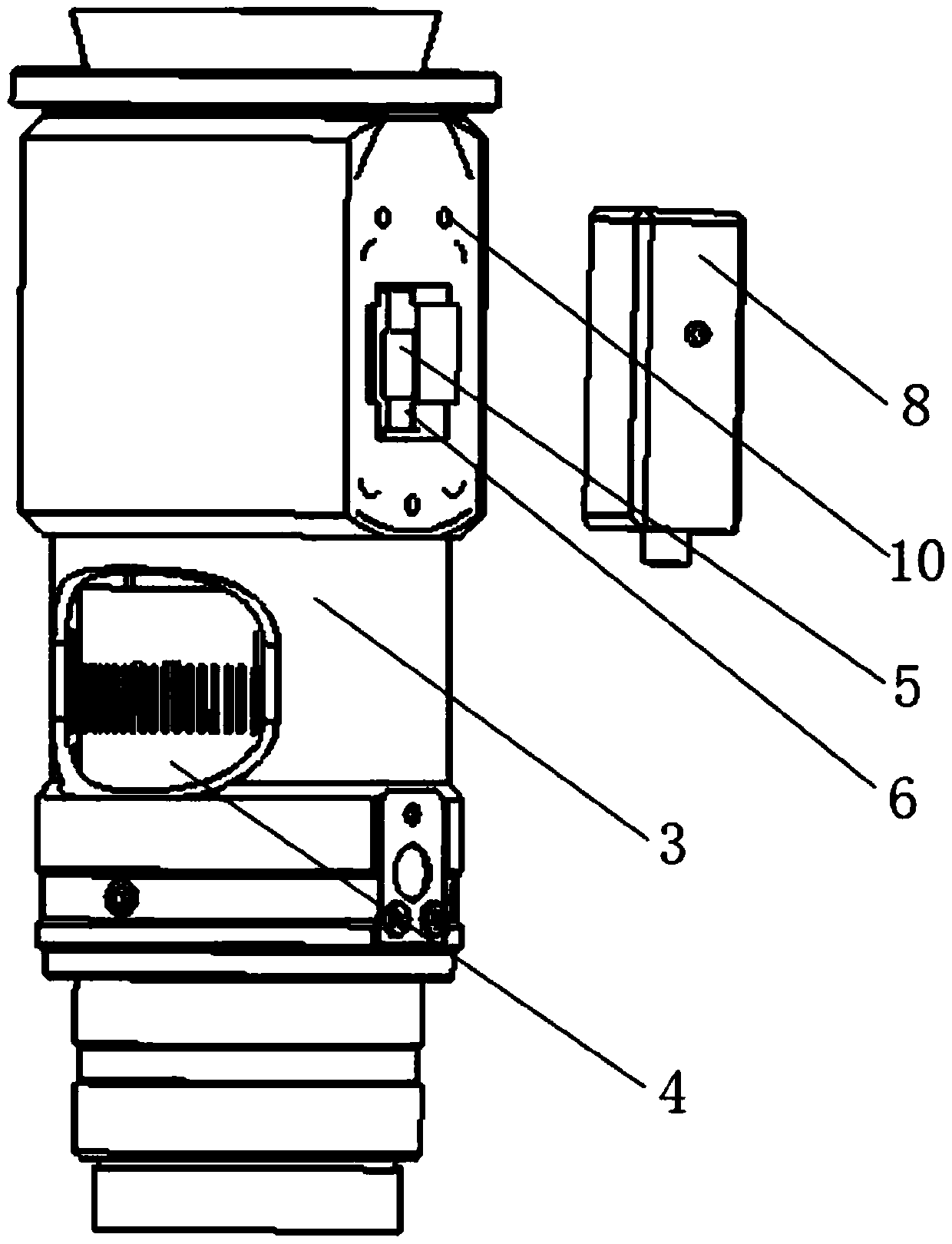
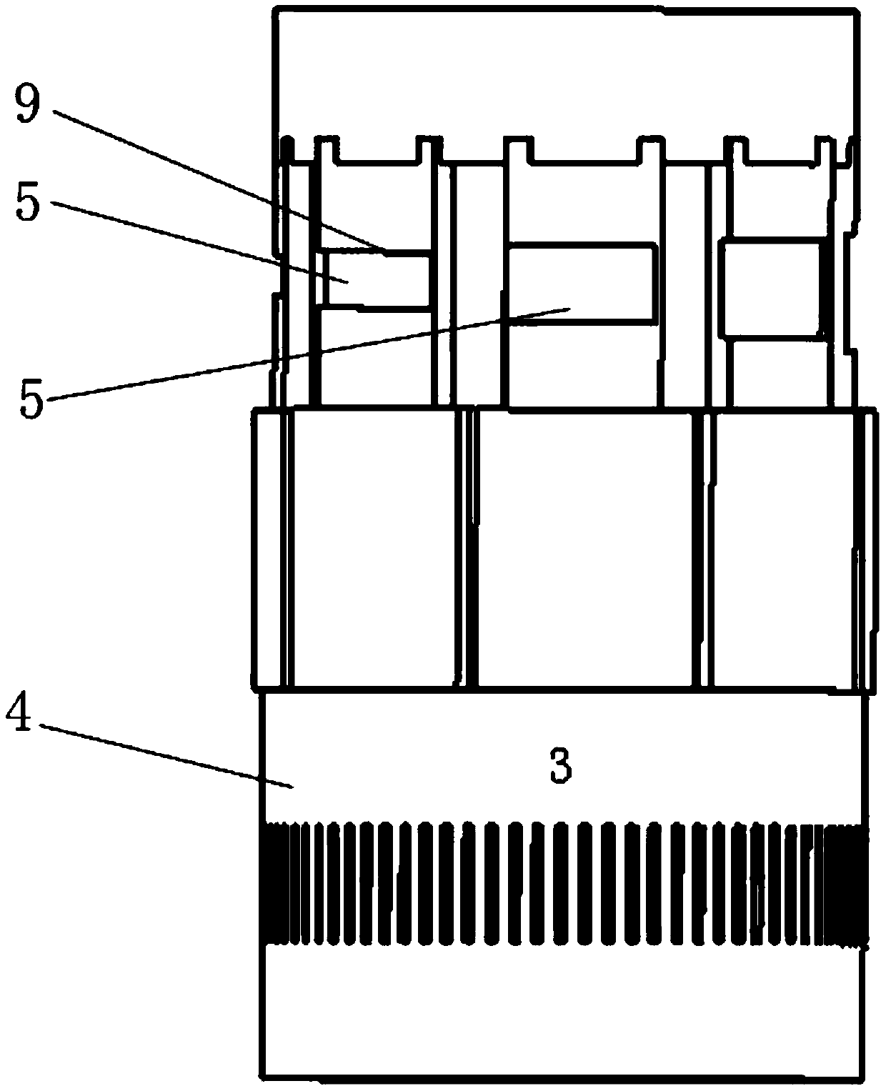
[0020] Such as Figure 1 ~ Figure 4 As shown, a manual zoom lens with electronic feedback based on light intensity of the present invention includes a main body of the manual zoom lens and an electronic feedback device connected to it, and the electronic feedback device is connected to the lower-level equipment (not shown in the figure) , the lower-level equipment uses a single-chip microcomputer; the main body of the manual zoom lens includes a lens adapter 1, an upper lens barrel 2, and a lower lens barrel 3 that are sequentially connected from top to bottom. The rotating shaft sleeve 4 passes through the lower lens barrel 3 and is rotatably connected with the upper lens barrel 2. The upper part of the rotating shaft sleeve 4 is equipped with optical signal reflectors 5 in an annular space. The reflective areas of each optical signal reflector 5 are different, and the corresponding optical signal The upper lens barrel 2 at the reflector 5 is provided with a light opening 6, ...


PUM


Abstract

The invention provides a light intensity-based electronic feedback manual zoom lens, which is convenient to operate, stable in performance, simple in structure and low in cost, and is capable of effectively reducing the unreliability of human operation and greatly improving the work efficiency. The light intensity-based electronic feedback manual zoom lens comprises a manual zoon lens main body and an electronic feedback device connected with the manual zoon lens main body, wherein the manual zoon lens main body comprises a lens adapter, an upper lens barrel and a lower lens barrel, which aresequentially connected and arranged from top to bottom; a rotating shaft sleeve is rotationally connected with the inside of the upper lens barrel; optical signal reflectors are also arranged on the rotating shaft sleeve at intervals in a ring; light passing holes are formed in the upper lens barrel corresponding to the optical signal reflectors; the electronic feedback device comprises an electronic feedback base, an optical signal transmitting unit, an optical signal receiving unit and a signal processing unit; the optical signal transmitting unit, the optical signal receiving unit and the signal processing unit are arranged on the electronic feedback base; the electronic feedback base is fixed on an outer wall of the upper lens barrel; the optical signal transmitting unit and the optical signal receiving unit are toward the optical signal reflectors through the light passing holes; and the optical signal receiving unit is connected with a subordinate device.

Description

technical field [0001] The invention relates to the technical field of optical equipment, in particular to an electronic feedback manual zoom lens based on light intensity. Background technique [0002] In the prior art, when the manual continuous zoom lens is used in various measurement environments, most of them rely on manual visual reading of the magnification value of the current position of the lens indicated on the scale circle of the lens, and then the read current position of the lens Manually input the magnification value of the lens to the lower-level equipment (mostly PC) connected to the lens, but in this process, it is difficult to ensure accurate information on whether the lens is adjusted to the exact position of the current magnification when adjusting the magnification, and errors are prone to occur Read the situation of the magnification value of the lens, and every time the lens is adjusted, it is necessary to manually read the magnification value of the ...

Claims


Application Information

Patent Timeline
Patent Type & Authority Applications(China)
IPC IPC(8): G01M11/02G02B7/04G05B19/042
CPCG01M11/0207G01M11/02G02B7/04G05B19/042G05B2219/25033
Inventor 王志伟于迪迪朱小琴王艳
Owner TZTEK TECH
Why Eureka
Try Eureka