
Air purification device beneficial to environmental protection and used for production factory

An air purification device and technology for environmental protection, applied in the field of air purification, can solve problems such as energy waste, increase in plant pressure, uneconomical, etc., and achieve the effects of convenient and flexible installation, avoiding loss and waste, and improving work quality.

Active Publication Date: 2020-01-03
安徽鑫德钙业有限公司
View PDF6 Cites 2 Cited by
  • Summary
  • Abstract
  • Description
  • Claims
  • Application Information

AI Technical Summary

Problems solved by technology

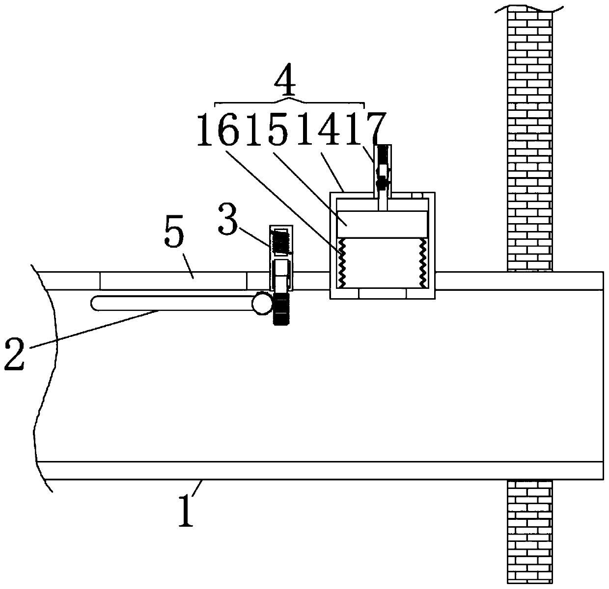
[0002] Production-type factories in the prior art will use air purification devices. By connecting an air injection pipe at one end of the delivery room and an exhaust pipe at the other end of the factory building, the air pump will push the outside air into the factory building and squeeze out the airflow in the factory building. To complete the entire air replacement and purification work, the existing problem is that if the airflow of the air injection pipe is injected too hard, it will cause the air pressure in the workshop to rise, which will not have much impact on the air purification work, but will cause a waste of energy, which is very uneconomical. For this reason, we Provided is an air purification device for a production factory that is beneficial to environmental protection

Method used


Image

  • Air purification device beneficial to environmental protection and used for production factory
  • Air purification device beneficial to environmental protection and used for production factory
  • Air purification device beneficial to environmental protection and used for production factory

Examples


Embodiment Construction

[0018] The following will clearly and completely describe the technical solutions in the embodiments of the present invention with reference to the accompanying drawings in the embodiments of the present invention. Obviously, the described embodiments are only some, not all, embodiments of the present invention. Based on the technical solutions in the present invention, all other embodiments obtained by persons of ordinary skill in the art without making creative efforts belong to the protection scope of the present invention.

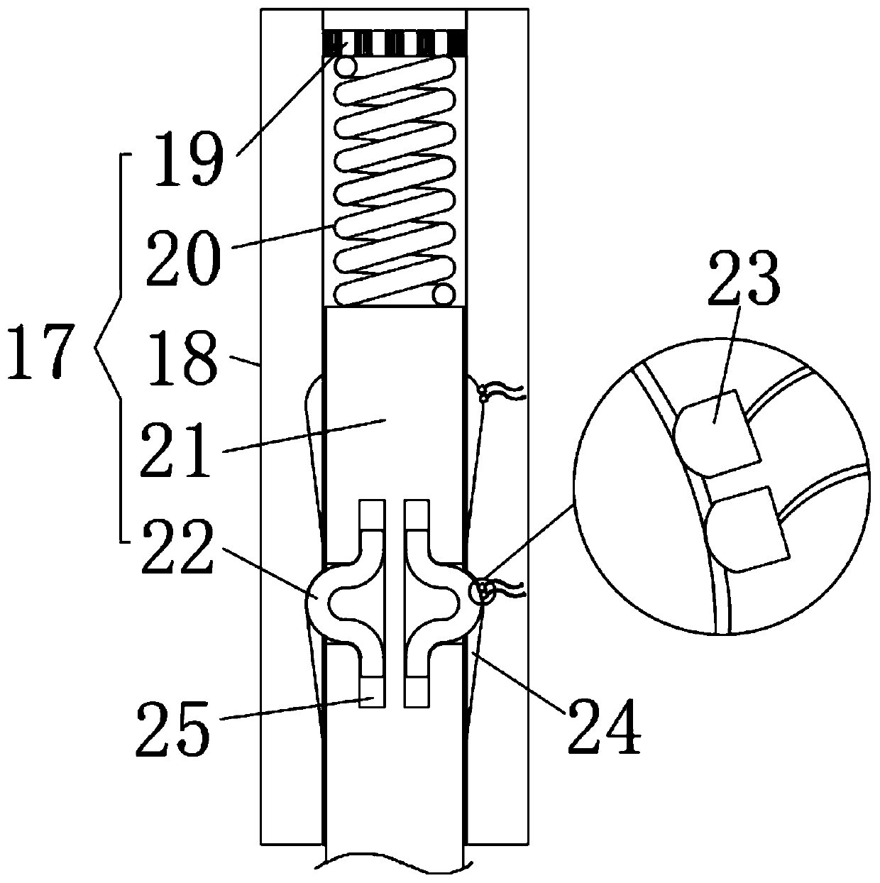
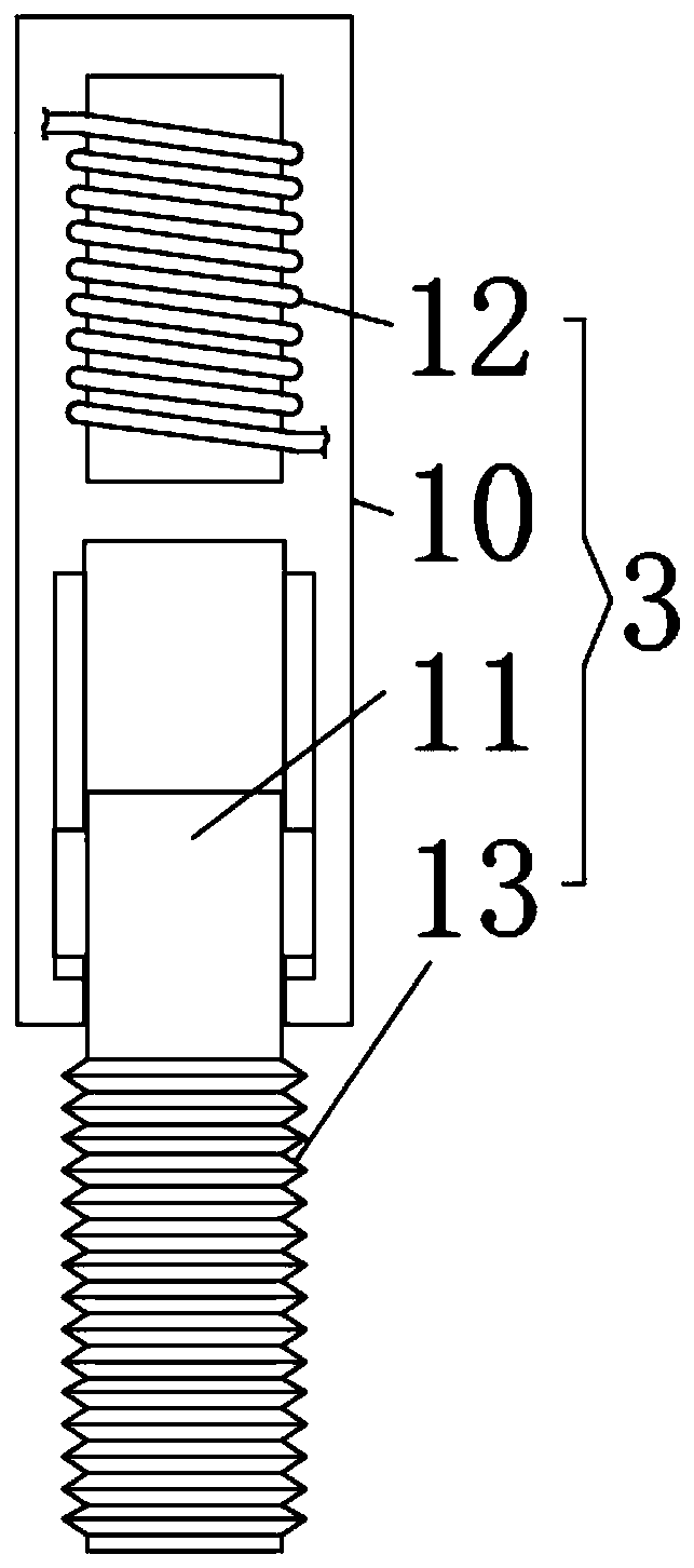
[0019] see Figure 1 to Figure 4 , the present invention provides a technical solution: a production-type factory air purification device that is beneficial to environmental protection, including a square tubular gas injection pipe 1, the gas injection pipe 1 is provided with a guide device 2, a pressure device 3 and a control device 4, and the guide The device 2 is located in the inner cavity of the gas injection pipe 1, and the gas injection pipe 1 o...


PUM


Abstract

The invention relates to the technical field of air purification, in particular to an air purification device beneficial to environmental protection and used for a production factory. The air purification device comprises a square tubular air-injection pipe. A guide device, a pressure device and a control device are arranged on the air-injection pipe. The guide device is located in an inner cavityof the air-injection pipe. A square exhaust hole is formed in the air-injection pipe and is located on one side of the guide device. One end of the guide device is in transmission connection with thepressure device. The pressure device penetrates through the side wall of the air-injection pipe. The control device is arranged on one side of the pressure device. The guide device comprises a rotaryshaft, a partition plate and Y-shaped teeth. According to the air purification device, the flowing direction of an air flow in the air-injection pipe is guaranteed through stable pneumatic control, the air pressure in the factory is prevented from being too high, and the influence of an excessively-high pressure on the whole purification work is small; energy losses and waste are avoided throughairflow transfer, so that energy saving and environmental protection effects are realized; and the air purification device is an independent working unit and has the advantages of being convenient andflexible to install.

Description

technical field [0001] The invention relates to the technical field of air purification, in particular to a production-type factory air purification device which is beneficial to environmental protection. Background technique [0002] Production-type factories in the prior art will use air purification devices. By connecting an air injection pipe at one end of the delivery room and an exhaust pipe at the other end of the factory building, the air pump will push the outside air into the factory building and squeeze out the airflow in the factory building. To complete the entire air replacement and purification work, the existing problem is that if the airflow of the air injection pipe is injected too hard, it will cause the air pressure in the workshop to rise, which will not have much impact on the air purification work, but will cause a waste of energy, which is very uneconomical. For this reason, we Provided is an air purification device for a production factory that is be...

Claims


Application Information

Patent Timeline
Patent Type & Authority Applications(China)
IPC IPC(8): F24F7/06F24F11/89
CPCF24F7/08F24F11/72F24F11/89
Inventor 姚帅锋陈鑫淑
Owner 安徽鑫德钙业有限公司
Learn More