
Engine

An engine and exhaust system technology, applied in the direction of engine components, engine control, combustion engine, etc., can solve the problems of small pressure difference between intake and exhaust systems, low engine exhaust pressure, and can not meet the needs of the engine, so as to increase exhaust Effects of back pressure, high EGR rate, and improved combustion economy

Inactive Publication Date: 2020-01-03
CHERY AUTOMOBILE CO LTD
View PDF7 Cites 0 Cited by
  • Summary
  • Abstract
  • Description
  • Claims
  • Application Information

AI Technical Summary

Problems solved by technology

Gasoline engines are divided into two types: naturally aspirated engines and supercharged engines. These two types of engines will encounter a problem when using EGR technology: when the engine is running at low speed and medium to high load, the exhaust of the engine will The air pressure is relatively low, the exhaust energy is weak, and the intake system does not form enough negative pressure because the throttle body is close to full opening. At this time, the pressure difference between the intake and exhaust systems is relatively small. Even if the EGR valve is fully opened, Also not much exhaust gas from the exhaust system can re-enter the intake system to participate in combustion
At this time, although the engine still has the potential to continue to increase EGR gas, due to the similar intake and exhaust pressures, there is not enough exhaust gas to enter the intake system, which cannot meet the engine's demand for reducing fuel consumption.

Method used


Image

  • Engine

Examples


Embodiment Construction

[0012] The specific embodiment of the present invention will be described in further detail by describing the embodiments below with reference to the accompanying drawings, the purpose is to help those skilled in the art to have a more complete, accurate and in-depth understanding of the concept and technical solutions of the present invention, and contribute to its implementation.

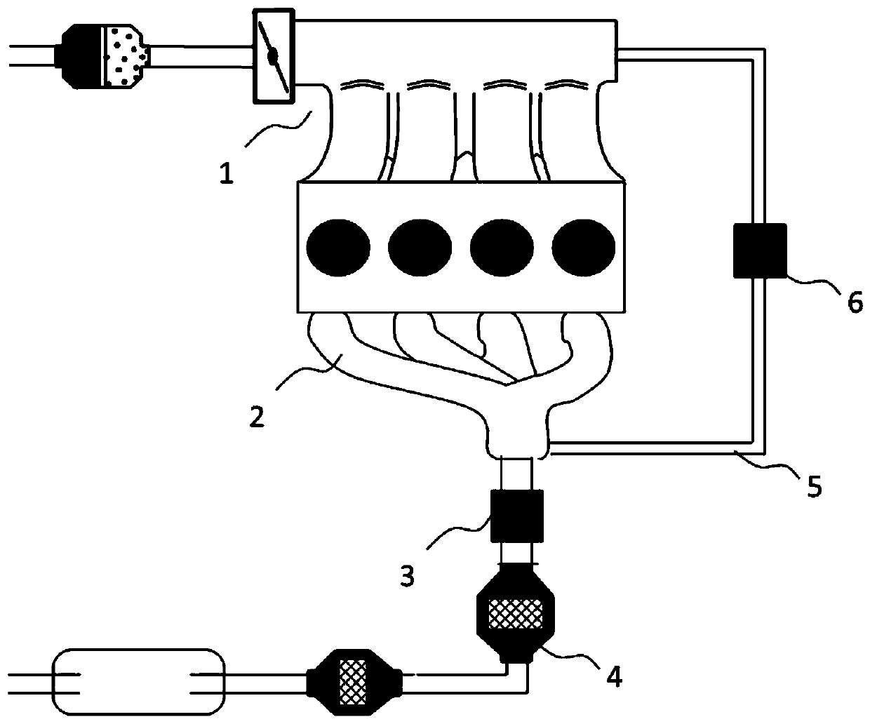
[0013] like figure 1 As shown, the present invention provides a kind of engine, comprises exhaust system, intake system 1 and the EGR valve 6 that is connected with exhaust system and intake system 1, when the pressure difference of exhaust system and intake system 1 reaches setting When the value is fixed, the exhaust back pressure of the exhaust system is increased to increase the amount of exhaust gas entering the intake system 1 through the EGR valve 6 .

[0014] Specifically, as figure 1 As shown, the exhaust system includes an exhaust manifold 2 and an exhaust back pressure regulating valv...


PUM


Abstract

The invention discloses an engine. An air outlet system, an air inlet system and an EGR valve are included, wherein the EGR valve is connected with the air outlet system and the air inlet system. Whenthe pressure difference of the air outlet system and the air inlet system reaches the set value, the air outlet backpressure of the air outlet system is increased, and accordingly the amount of wastegas entering the air inlet system through the EGR valve is increased. According to the engine, in the high load work condition at the engine low rotation speed, the air outlet backpressure is increased, and the purpose of higher EGR efficiency is achieved. The scheme is simple and reliable, combustion economical efficiency of the engine is improved, and the economical efficiency of the engine ishigh.

Description

technical field [0001] The invention relates to an engine. Background technique [0002] Due to the increasingly stringent regulations, the requirements for engine fuel consumption and emissions are getting higher and higher. The application of EGR (Exhaust Gas Recirculation) technology has become an important technical means for reducing fuel consumption and emissions of gasoline engines today. It is significantly reducing NOx While reducing emissions, it also improves engine combustion economy. [0003] EGR technology has been widely used in gasoline engines. Gasoline engines are divided into two types: naturally aspirated engines and supercharged engines. These two types of engines will encounter a problem when using EGR technology: when the engine is running at low speed and medium to high load, the exhaust of the engine will The air pressure is relatively low, the exhaust energy is weak, and the intake system does not form enough negative pressure because the throttle...

Claims


Application Information

Patent Timeline
Patent Type & Authority Applications(China)
IPC IPC(8): F02D9/04F02M26/14F02M26/16F01N3/10F01N13/10
CPCF01N3/101F01N13/10F02D9/04F02M26/14F02M26/16Y02T10/12
Inventor 金晖王伟陈伟国李玉琦
Owner CHERY AUTOMOBILE CO LTD
Learn More