


Quick Research
Generate reliable direction feasibility study reports for your R&D in just a few steps.

Technical Q&A
Discover and master advanced knowledge NOW. Basics, ideas, possibilities, all at once.

Find Solutions
As an expert in R&D theories, this can generate solutions to your technical problems instantly.

Evaluate Feasibility
Analyze your overall solution with one click, know your potential R&D risks in advance.

Monitor Landscape
Get weekly tech updates, stay abreast of the latest tech innovations and key insights.
Z-shaped strip working face mining method
A mining method and working face technology, applied in ground mining, mining equipment, earthwork drilling, etc., can solve the problems of low cost of roadway retention and high roadway excavation rate, and achieve the effects of simple construction, reduced support cost, and reduced employment.
- Summary
- Abstract
- Description
- Claims
- Application Information
AI Technical Summary
Problems solved by technology
Method used
Image

Examples
Embodiment 1
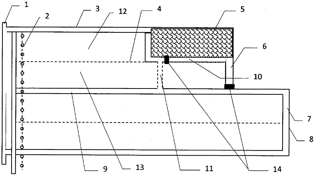
[0022] like figure 1 As shown, in a mining area, the front end is the system main road 1 and the main road coal pillar 2, the mining area is divided into several strip groups, each strip group includes a strip working face 12 and its adjacent strip coal Column 13, there is a strip working face boundary 4 between the strip working face 12 and the strip coal pillar 13, and the rear end of the strip working face 12 is the goaf 5; The belt return 9 and the boundary return air lane 6 of a strip group, the strip run 3 of the next strip group overlaps or partially overlaps with the strip return 9 of the previous strip group.
[0023] Strip mining: The return air lane 6 at the boundary of the strip group is transported from the strip along 3 to the boundary line 4 of the strip working face as the cutting hole position of the strip working face to form a Z-shaped mining layout. The reserved entry 10 at the boundary position of the coal pillar 13 in the head strip communicates with the...
Embodiment 2
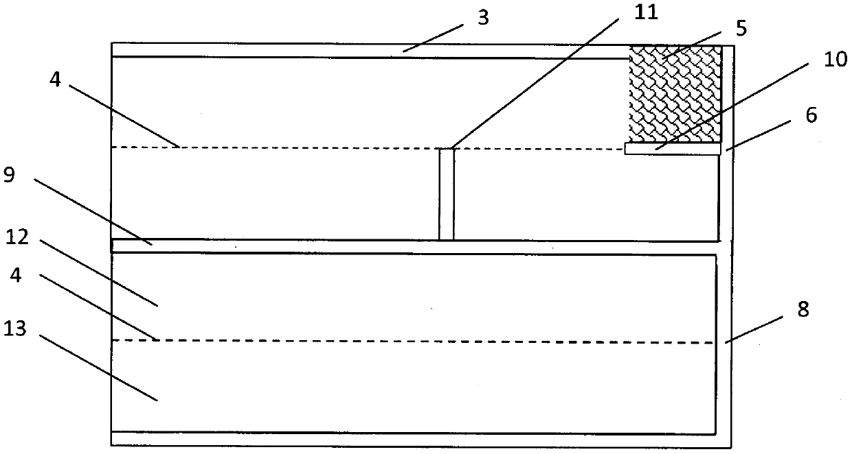
[0033] like figure 2 As shown, in a mining area, the front end is the system main road 1 and the main road coal pillar 2, the mining area is divided into several strip groups, each strip group includes a strip working face 12 and its adjacent strip coal Column 13, there is a strip working face boundary 4 between the strip working face 12 and the strip coal pillar 13, and the rear end of the strip working face 12 is the goaf 5; The strip return 9 and a strip group boundary return air lane 6, the strip run 3 of the next strip group coincides with the strip return run 9 of the previous strip group.
[0034] Strip mining: The return air lane 6 at the boundary of the strip group is transported from the strip along 3 to the boundary line 4 of the strip working face as the cutting hole position of the strip working face to form a Z-shaped mining layout. The reserved entry 10 at the boundary position of the coal pillar 13 in the headband is communicated with the return air entry 6 a...
Embodiment 3
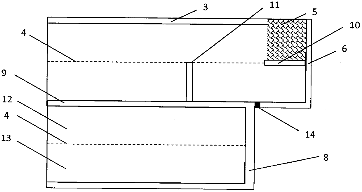
[0042] like image 3 As shown, in a mining area, the front end is the system main road 1 and the main road coal pillar 2, the mining area is divided into several strip groups, each strip group includes a strip working face 12 and its adjacent strip coal Column 13, there is a strip working face boundary line 4 between the strip working face 12 and the strip coal pillar 13, and the rear end of the strip working face 12 is the goaf 5; The strip return 9 and the boundary return air lane 6 of a strip group, the strip run 3 of the next strip group partially overlaps with the strip return run 9 of the previous strip group.
[0043]Take the return airway 6 at the boundary of the strip group from Yunshun 3 of the strip to the boundary line of the coal pillar of the strip as the opening position of the strip working face to form a Z-shaped mining layout, and the coal pillar at the end of the working face during the mining process 13 The boundary position is reserved and the lane 10 com...
PUM
 Abstract
Description
Claims
Application Information
 - R&D Engineer
- R&D Manager
- IP Professional
- Industry Leading Data Capabilities
- Powerful AI technology
- Patent DNA Extraction
Browse by: Latest US Patents, China's latest patents, Technical Efficacy Thesaurus, Application Domain, Technology Topic, Popular Technical Reports.
© 2024 PatSnap. All rights reserved.Legal|Privacy policy|Modern Slavery Act Transparency Statement|Sitemap|About US| Contact US: help@patsnap.com