A tire mold cutting plotter

A technology for tire molds and cutting plotters, which is applied in the direction of manufacturing tools, metal processing machinery parts, metal processing, etc., can solve the problems of troublesome operation, high labor intensity, heavy tire molds, etc., and achieve the effect of reducing friction and facilitating processing.

Active Publication Date: 2021-03-26
青岛强林机械科技有限公司
View PDF1 Cites 0 Cited by
  • Summary
  • Abstract
  • Description
  • Claims
  • Application Information

AI Technical Summary

Problems solved by technology

[0004] The above existing technical solutions have the following defects: every time the tire mold is loaded and unloaded, the operator needs to manually place the tire mold from the ground on the rotary table for fixing or clamping, or the operator manually places the tire mold on the rotary table. The tire mold is unfixed or loosened from the rotary table, and then the tire mold mold is placed on the ground, so the operation is more troublesome, and because the tire mold is heavier, the labor intensity is higher

Method used


Image

  • A tire mold cutting plotter
  • A tire mold cutting plotter
  • A tire mold cutting plotter

Examples


Embodiment Construction

[0037] The present invention will be described in further detail below in conjunction with the accompanying drawings.

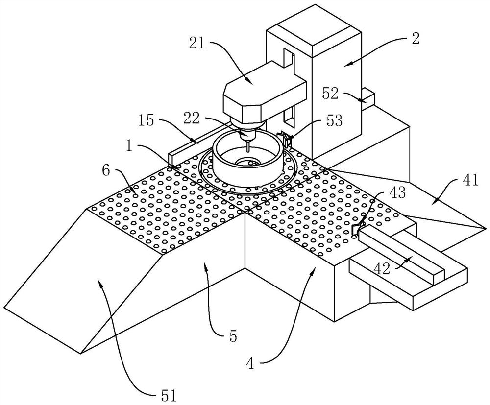
[0038] refer to figure 1 , is a cutting plotter for tire molds disclosed by the present invention, including a base 1, a stand 2 is vertically fixed on one side of the base 1, and a vertically slidably connected side of the stand 2 close to the base 1 is connected with a horizontally arranged Lifting arm 21, a lift cylinder (not shown) that can drive lifting arm 21 to slide vertically is also provided in the stand 2, and the lower side of one end of lifting arm 21 away from the stand 2 is fixedly connected with a lettering head 22 (Here is the existing technology and will not go into details here). During work, the tire mold is placed on the base 1, and the lettering head 22 is driven up and down by the lifting cylinder, the height of the lettering head 22 can be adjusted, and then the tire mold can be processed through the lettering head 22 .

[0039] refe...


PUM


Abstract

The invention relates to a tire mold character engraving machine. The tire mold character engraving machine comprises a base. A vertical frame is fixedly connected to one side of the base, and a character engraving head is arranged on the upper side of the vertical frame. A receiving disc is arranged on the upper side of the base. A feeding platform is fixedly connected with one side of the base,and a material push mechanism is arranged on one side of the feeding platform. At least three sliding grooves are evenly formed in the upper side of the receiving disc, threaded rods are connected with the lower sides of the corresponding sliding grooves of the receiving disc in a rotating mode, clamping blocks are connected with the interiors of the sliding grooves in a sliding mode and connectedto the corresponding threaded rods in a threaded mode, and first bevel gears are fixedly connected with the lower ends of the threaded rods. Reversing shafts are connected with the portions, corresponding to the threaded rods, of the receiving disc in a rotating mode, second bevel gears are fixedly connected with the upper ends of the reversing shafts, third bevel gears are fixedly connected withthe lower ends of the reversing shafts, and a fourth bevel gear is further connected with the middle of the receiving disc in a rotating mode. A material receiving platform is fixedly connected withthe side, far away from the vertical frame, of the base, and a material return mechanism is further arranged on the side, close to the base, of the vertical frame. The tire mold character engraving machine has the effects that the labor intensity of an operator can be reduced, operation is easy, and utilization is convenient.

Description

technical field [0001] The invention relates to the technical field of tire mold processing, in particular to a cutting plotter for tire molds. Background technique [0002] With the rapid development of the automobile industry, new varieties of tires, which are important parts of automobiles, are constantly emerging, and the launch cycle is getting shorter and shorter. A large proportion of changes in new tire varieties is reflected in changes in tire patterns. Before producing tires, it is necessary to use The milling machine first mills the pattern on the circumferential surface of the inner cavity of the tire mold. After milling the pattern, it is generally necessary to use a tire mold cutting plotter to engrave the logo, model, etc. used to identify the tire in the tire mold, so that through the tire mold processing The model product of the tire can be reflected on the surface of the tire. [0003] The existing reference application publication number is: the Chinese i...

Claims


Application Information

Patent Timeline
Patent Type & Authority Patents(China)
IPC IPC(8): B23D79/00B23Q7/00B23Q3/06B23Q1/26
CPCB23D79/00B23Q1/26B23Q3/062B23Q7/00
Inventor 任昌强孙妹李静
Owner 青岛强林机械科技有限公司
Why Eureka
Try Eureka