
Ball valve type shielding transfer device

A transfer device and ball valve technology, applied in nuclear engineering, portable protective containers, etc., can solve problems such as unfavorable maintenance of air pressure stability in closed chambers, unsuitable transfer methods and equipment, leakage of radioactive substances, etc., to avoid radiation pollutants Outflow, protection of occupational radiation health, effect of radiation safety protection

Inactive Publication Date: 2019-12-31
NUCLEAR POWER INSTITUTE OF CHINA
View PDF7 Cites 2 Cited by
  • Summary
  • Abstract
  • Description
  • Claims
  • Application Information

AI Technical Summary

Problems solved by technology

[0003] In the practice of long-term design, manufacture, installation and use, and later maintenance, the traditional transfer channel has many disadvantages and shortcomings, including inconvenient operation, poor versatility, difficult maintenance and overhaul, and it is not conducive to maintaining the stability of the air pressure in the airtight chamber. It is easy to cause the leakage of radioactive substances, etc.
[0004] In nuclear facilities or radioactive sites, shielded transfer channels are used more and more, and with the development of society, the requirements for it are getting higher and higher. Traditional transfer methods and equipment are no longer suitable for current practice. demand, there is an urgent need for a new type of transfer device to meet the needs of the market, and the present invention just fills this gap

Method used

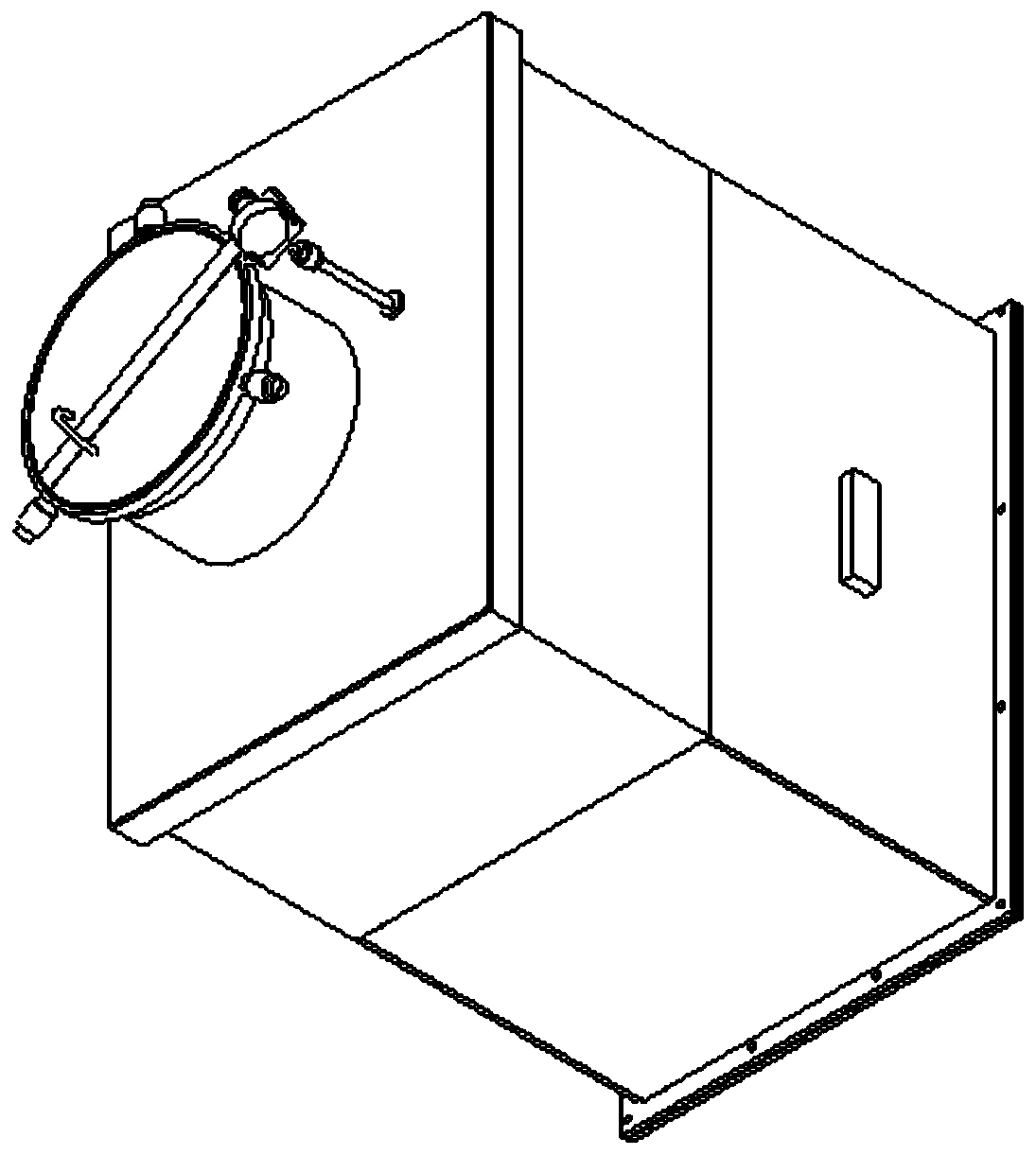
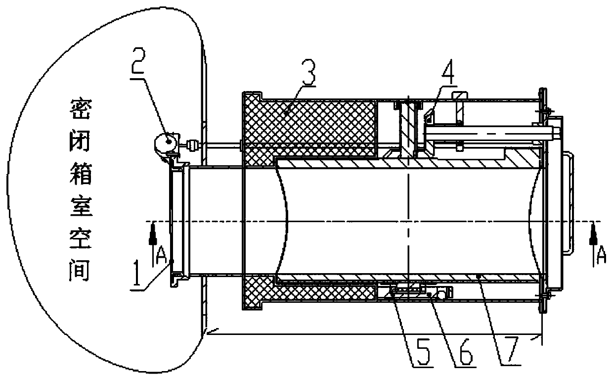
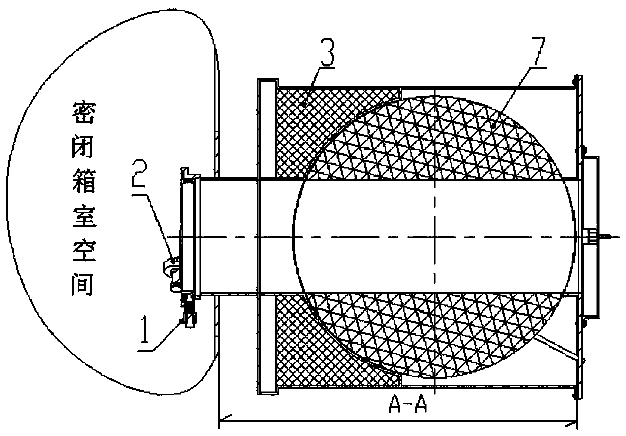

Image

  • Ball valve type shielding transfer device
  • Ball valve type shielding transfer device
  • Ball valve type shielding transfer device

Examples


Embodiment Construction

[0025] In order to understand the above-mentioned purpose, features and advantages of the present invention more clearly, the present invention will be further described in detail below in conjunction with the accompanying drawings and specific embodiments. It should be noted that, under the condition of not conflicting with each other, the embodiments of the present application and the features in the embodiments can be combined with each other.

[0026] In the following description, many specific details are set forth in order to fully understand the present invention. However, the present invention can also be implemented in other ways different from the scope of this description. Therefore, the protection scope of the present invention is not limited by the following disclosure. limitations of specific examples.

[0027] Please refer to Figure 1-Figure 3 , a ball valve-type shielded transfer channel provided by the present invention is mainly used in radioactive faciliti...


PUM


Abstract

The invention discloses a ball valve type shielding transfer device. The device comprises a shielding valve core, a shielding valve body, a valve core rotating assembly, a valve core installation auxiliary assembly, a valve core operation assembly, a sealing cover assembly, an operation mooring rope mechanism and a sealing assembly of the operation mooring rope mechanism, wherein the valve core installation auxiliary assembly is used for installing the shielding valve core and the valve core rotating assembly into the shielding valve body; the shielding valve core can rotate through the valvecore rotating assembly; a first channel is formed in the shielding valve body; a second channel is formed in the shielding valve core; when the shielding valve core rotates to a first preset position,the first channel and the second channel are communicated with each other to form a transfer channel; the valve core operation assembly is used for driving the shielding valve core to rotate under the traction of an operation mooring rope; and the sealing cover assembly is used for sealing the transfer channel. The device realizes the optimization of radiation protection and transfer operation.

Description

technical field [0001] The invention relates to the field of radioactive objects entering and exiting closed chambers in radioactive facilities, in particular to a ball valve type shielding transfer device. Background technique [0002] In radioactive facilities (including nuclear power plants, research reactors, experimental reactors, radiation inspection and test facilities, radioactive waste treatment facilities, radioactive material production plants, radiotherapy sites, radioactive animal and plant research sites, and other radioactive scientific research and test facilities), when When the radioactive level of the processed material (gamma radiation, neutron radiation or mixed radiation) reaches a certain level, appropriate radiation protection measures need to be taken to protect the radiation safety and radiation safety of personnel and the environment. Generally speaking, shielding, distance and time control will be used comprehensively in the process. Depending on ...

Claims


Application Information

Patent Timeline
Patent Type & Authority Applications(China)
IPC IPC(8): G21F5/14G21F5/12
CPCG21F5/12G21F5/14
Inventor 王育坤吕仙镜汪海李明冯艳明吴红伟司丹丹
Owner NUCLEAR POWER INSTITUTE OF CHINA
Learn More