
Fusing device for strapping tape baler

A fusion device and strapping technology, which is applied to the parts of the strapping machine, etc., can solve the problems of difficulty in adjusting and controlling the lifting distance of the welding upper teeth, the single type of fusion device, and the difficulty of manufacturing and maintenance, so as to improve work independence, The effect of ensuring accuracy and smooth motion, reducing the difficulty of manufacturing and maintenance

Pending Publication Date: 2019-12-31
青岛亚特利智能包装科技有限公司
View PDF0 Cites 11 Cited by
  • Summary
  • Abstract
  • Description
  • Claims
  • Application Information

AI Technical Summary

Problems solved by technology

[0003] However, at present, the fusion device of the portable strapping machine has a single type and a high degree of integration. The welding operation of the strapping belt and the up and down swing of the welding upper teeth (that is, the switching operation of the welding position) are connected to the transmission. Although the degree of automation is high, this setting not only Manufacturing and maintenance are difficult, maintenance cost is high, failure rate is high, and it is difficult to control the lifting distance of the welding upper teeth

Method used


Image

  • Fusing device for strapping tape baler
  • Fusing device for strapping tape baler
  • Fusing device for strapping tape baler

Examples


Embodiment 1

[0058] Such as Figure 8-14 As shown, the present embodiment provides a fusion device for a strapping machine, which includes:

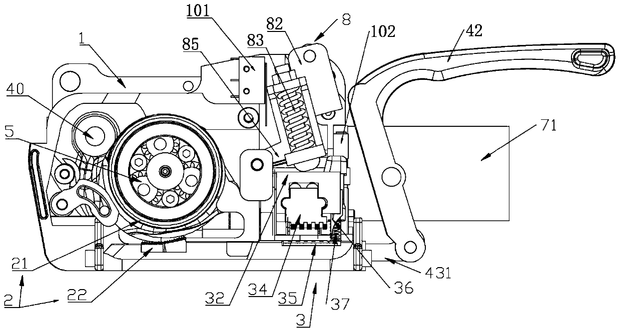
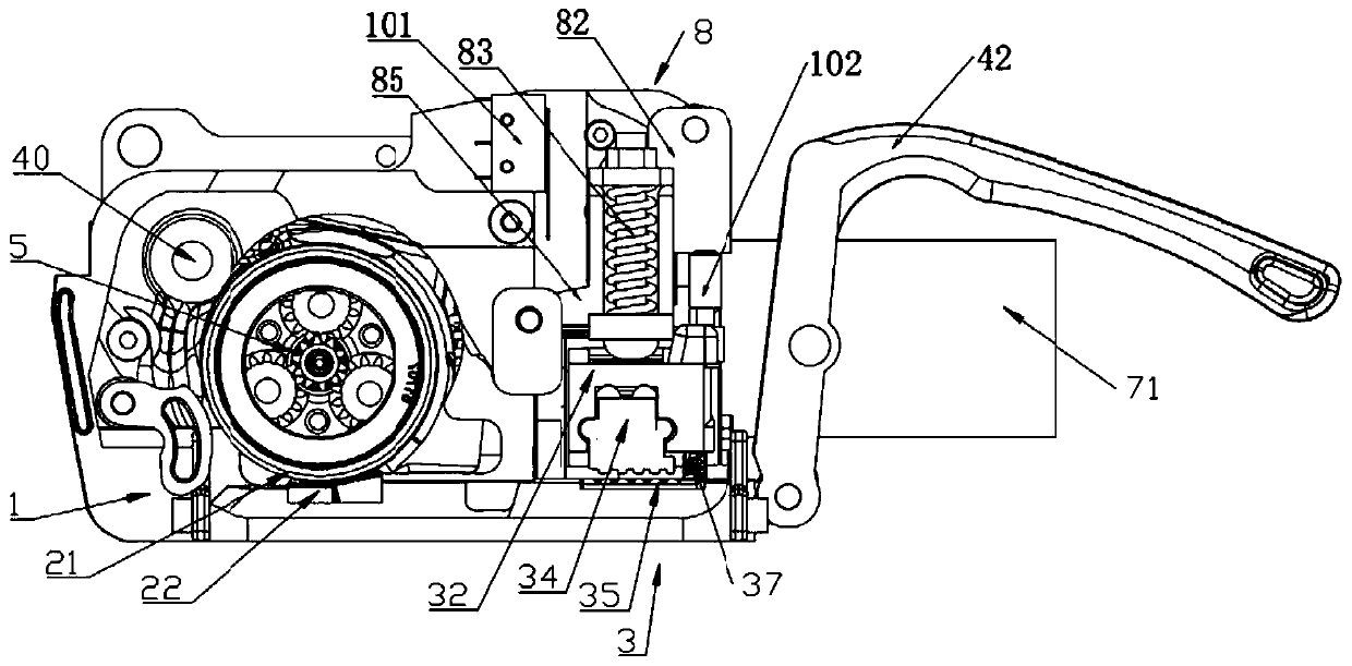
[0059] The strap welding mechanism 3 is used to form the friction welding connection at the overlapping position of the strap rings, and the welding state switching mechanism 8 is used to switch the strap welding mechanism 3 between the welding position and the rest position. Through the cooperation of the above two mechanisms, friction welding is performed on the overlapping area of ​​the strapping rings on the strapping strap welding mechanism 3 on the baler. The fusion device can be applied to various balers, and used in conjunction with other belt tensioning mechanisms of the baler to complete the overall baling of the strapping. The details of the structure of each part of the fusion device are as follows:

[0060] Strap welding mechanism

[0061] Such as Figure 8-10 As shown, the strap welding mechanism 3 includes an eccentric shaft 31 arr...

Embodiment 2

[0075] Such as Figure 1-2 In the shown embodiment, there is provided a portable baler using the above-mentioned fusion device, the baler includes a machine base 1, a strap tightening mechanism 2 arranged on the machine base 1, a take-up wheel lifting mechanism 4 and Strap welding mechanism3. Wherein, the base 1 is used as a skeleton structure for fixing other various structures.

[0076] The strap tightening mechanism 2 includes: a tightening wheel 21 driven by rotation, and a tightening plate 22 located below the tightening wheel 21 . The endless binding belt clamped between the tightening wheel 21 and the tightening plate 22 is tightened under the rotation of the tightening wheel 21 .

[0077] The strapping welding mechanism 3 is configured to form a stable friction welding connection at overlapping positions of the strapping loops through friction welding elements.

[0078] The take-up wheel lifting mechanism 4 includes: one end is pivotally connected with the support t...

Embodiment 3

[0110] Figure 17-19 The illustrated portable packer is a variant of Embodiment 1. Different from Embodiment 1, the second driving mechanism 72 in this embodiment is arranged in parallel with the first driving mechanism 71 . The plane where the swing bracket 82 swings is perpendicular to the plane where the swing seat 41 (or tightening wheel) is located, and the second drive mechanism 72 drives the swing bracket 82 to swing through the rotation of the eccentric wheel provided on its output shaft, so that the swing bracket The lower swing of the upper pressing column presses toward the welding frame or the upper swing moves away from the welding frame, thereby realizing the switch between the rest position and the welding position of the strap welding mechanism 3 .

[0111] In this embodiment, in order to simplify the structure, the welding state conversion mechanism adopts the following Figure 20-21 structure shown. Only one lower roller 842 is arranged on the swing bracke...


PUM


Abstract

The invention discloses a fusing device for a strapping tape baler. The fusing device comprises a strapping tape welding mechanism and a welding state switching mechanism. The strapping tape welding mechanism forms friction welding connection at the overlapping position of a strapping tape loop, and comprises a welding frame, welding upper teeth positioned on the welding frame, and welding lower teeth connected to a machine base. The welding upper teeth on the welding frame are driven by a first driving mechanism to vibrate back and forth relative to the welding lower teeth for welding. The welding state switching mechanism is driven by a second driving mechanism, and comprises an eccentric wheel driven by the second driving mechanism, a swing support driven by the rotating of the circumferential surface of the eccentric wheel, and a pressing column arranged on the swing support. The swing trajectory of the bottom of the pressing column passes through the top face of the welding frame.The swing support is driven to swing up and down by the rotating of the eccentric wheel. The welding frame is pressed at the welding position or the return stop position through the pressing column.The strapping tape welding mechanism and the welding state switching mechanism are independently driven, the maintenance difficulty and cost of the fusing device are reduced, and the control precisionis improved.

Description

technical field [0001] The invention relates to the technical field of strapping strapping machines, in particular to a fusion device for strapping strapping machines. Background technique [0002] With the rapid development of science and technology, various types of strapping equipment used in various fields and meeting different needs have appeared on the market. The commonly used bundling method is to use plastic strapping to wrap around the items to be packed. At present, the strapping machines that appear on the market usually tighten the strapping rings around the packed items and weld them by friction welding. Fusion permanently joins the overlapping leading portions of the strapping to complete the pack. Due to the convenience of using and moving the portable baler, the application of the portable baler is becoming more and more extensive. [0003] However, at present, the fusion device of the portable strapping machine has a single type and a high degree of integ...

Claims


Application Information

Patent Timeline
Patent Type & Authority Applications(China)
IPC IPC(8): B65B13/32B65B13/22
CPCB65B13/32B65B13/22
Inventor 严远忠彭向
Owner 青岛亚特利智能包装科技有限公司
Learn More