
Permanent magnet moving-coil type shock wave generating device

A generating device and shock wave technology, applied in vibration massage, fluid using vibration, physical therapy, etc., can solve the problems of relatively high power requirements, high requirements for shock wave vibration energy current and voltage, and large pulse current, etc., to achieve improvement Reliability and safety, power supply and system configuration requirements are small, and the effect of small pulse current

Pending Publication Date: 2019-12-31
SHENZHEN HUIKANG PRECISION APP
View PDF0 Cites 0 Cited by
  • Summary
  • Abstract
  • Description
  • Claims
  • Application Information

AI Technical Summary

Problems solved by technology

[0003] But the shock wave vibration energy of the prior art has high requirements on current and voltage, so that its service life and reliability have corresponding limitations. Large, and the coil is set close to the diaphragm, then the heat generated by its heating will be directly transferred to the propagation medium (such as: water), and then transferred to the human body. Therefore, a water circulation system needs to be installed in the water bag to achieve heat dissipation; Third, the electromagnetic shock wave source in the prior art has relatively high requirements on the supporting power supply

Method used


Image

  • Permanent magnet moving-coil type shock wave generating device
  • Permanent magnet moving-coil type shock wave generating device
  • Permanent magnet moving-coil type shock wave generating device

Examples


Embodiment Construction

[0025] The preferred embodiments of the present invention will be further described in detail below in conjunction with the accompanying drawings.

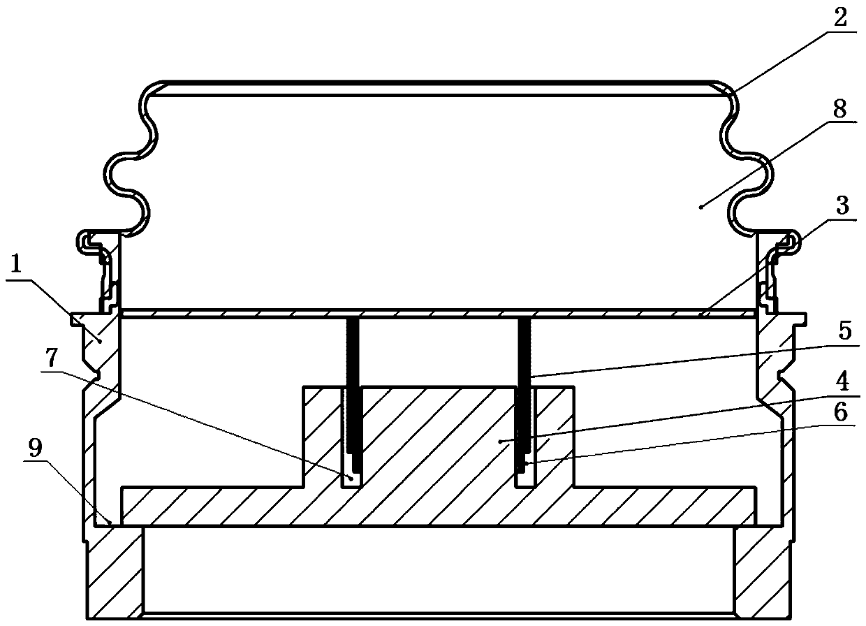
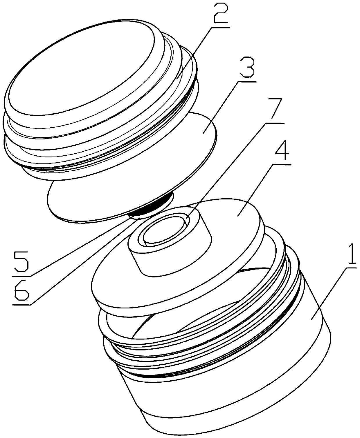
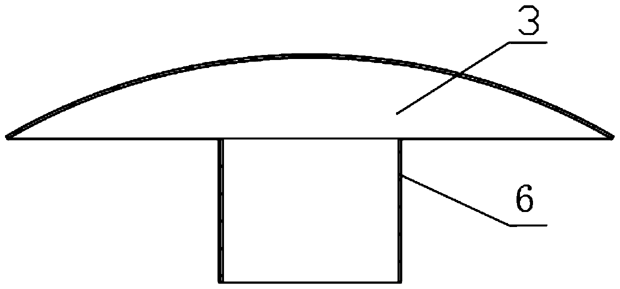
[0026] Such as figure 1 and figure 2 As shown, this example provides a permanent magnet moving coil type shock wave generating device, including: a cup body 1, a water bag 2, a diaphragm 3, a permanent magnet 4 and a coil 5, and the water bag 2 is arranged on the cup body 1 Above, the diaphragm 3 is arranged below the water bag 2, and the cavity between the water bag 2 and the diaphragm 3 is filled with a shock wave conducting medium; the upper part of the permanent magnet 4 is provided with an empty groove 7 , the coil 5 is fixedly arranged under the diaphragm 3 and placed in the cavity 7 of the permanent magnet 4; the permanent magnet 4 is arranged in the cup body 1 and arranged in the diaphragm 3 Below: when the coil 5 is energized, it generates a magnetic field with the same polarity direction as the permanent magnet 4 .

...


PUM


Abstract

The invention provides a permanent magnet moving-coil type shock wave generating device. The permanent magnet moving-coil type shock wave generating device comprises a cup, a water sac, a vibrating film, a permanent magnet and a coil, wherein the water sac is arranged on the cup; the vibrating film is arranged below the water sac; the coil is fixedly arranged below the vibrating film; the permanent magnet is arranged in the cup, and is arranged below the vibrating film; and when the coil is electrified, a magnetic field of which the polarity direction is the same as that of the permanent magnet is generated. According to the permanent magnet moving-coil type shock wave generating device disclosed by the invention, when the coil is electrified, under the effect of magnetic field of the permanent magnet, the coil is pushed by upward thrust in the direction of the axis of the coil; the coil is fixedly arranged below the vibrating film, so that under the driving of the coil, the vibratingfilm can produce pulse vibration to form a shock wave; and the permanent magnet is adopted, the magnetic flux density is large, the interaction of the induced magnetism field of the coil and the permanent magnet is violent, the kinetic energy transformation efficiency is high, and the effect of producing the shock wave is notable, so that the service life of the products can be effectively prolonged, and the reliability and the safety of the products are improved.

Description

technical field [0001] The invention relates to a medical shock wave generating device, in particular to a permanent magnet moving coil type shock wave generating device. Background technique [0002] Shock wave is a mechanical wave produced by sudden release in a confined space in gas or liquid. Its essence is a kind of energy transmission process. It has been widely used in clinical medicine now, mainly for the treatment of urinary stones, hepatobiliary system Calculus, fracture nonunion, femoral head necrosis, aseptic soft tissue injury and the pain caused by it, erectile dysfunction and cardiovascular function and other diseases. The existing electromagnetic shock wave source consists of a cup body, an electromagnetic disk, a lens and a water bag. The electromagnetic disk is fixedly installed at the bottom of the cup as a device for generating shock waves; a lens is arranged in the middle of the cup as a device for changing the direction of shock wave propagation; a wat...

Claims


Application Information

Patent Timeline
Patent Type & Authority Applications(China)
IPC IPC(8): A61H23/00A61H23/02B06B1/04
CPCA61H23/008A61H23/02B06B1/045A61H2201/5005A61H2201/123B06B2201/76
Inventor 江湛成李夫进杨辉陈明
Owner SHENZHEN HUIKANG PRECISION APP
Learn More