Screw compressor with multi-layer coated rotor screw

A technology for screw compressors and compressor housings, applied in the direction of rotary piston machinery, mechanical equipment, engine components, etc., to achieve the effects of reduced risk of coating swelling, high running stability, and good chemical resistance

Active Publication Date: 2021-08-27
凯撒空压机有限公司
View PDF1 Cites 0 Cited by
  • Summary
  • Abstract
  • Description
  • Claims
  • Application Information

AI Technical Summary

Problems solved by technology

Can be compressed in one or more stages

Method used


Image

  • Screw compressor with multi-layer coated rotor screw
  • Screw compressor with multi-layer coated rotor screw
  • Screw compressor with multi-layer coated rotor screw

Examples


Embodiment Construction

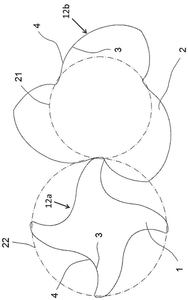
[0139] exist figure 1 An end surface cross section of a rotor screw pair according to the present invention is shown, and the rotor screw pair includes rotor screw 1, which is designed as a sub-rotor, and a rotor screw 2 designed as a main rotor. Only purely shown, the profile surfaces 12a, 12b of the rotor screws 1, 2 are respectively coated with the first inner layer 3 and the second outer layer 4, respectively. The rotor screws 1, 2 mesh each other, i.e., with its teeth to interleave with each other. For a feeding that has been mentioned, the fence for designing the rotor screw 1 designed as the sub-rotor is labeled with reference numeral 21, and the rotor screw 2 for designing as the main rotor is marked.

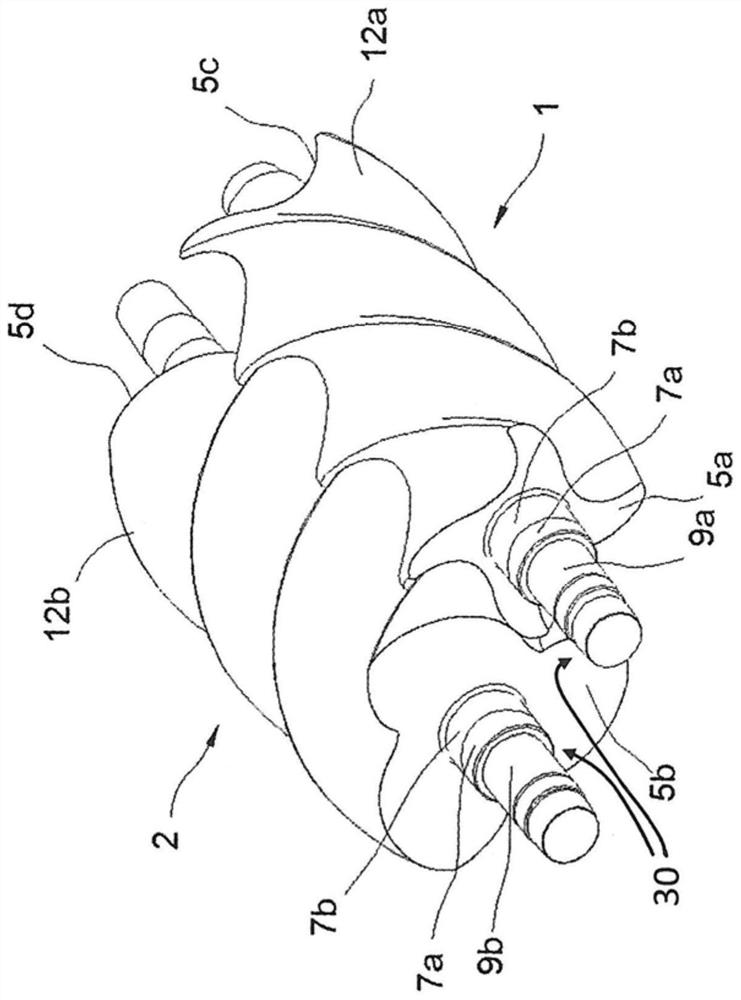
[0140] exist figure 2 In the perspective view, the rotor screws 1, 2 which are coupled to each other are shown. Here, the two rotor screws 1, 2 are interlaced from each other with the existing shaped curved surfaces 12a, 12b, or to each other, or to rotten into each other. ...


PUM

PropertyMeasurementUnit
thicknessaaaaaaaaaa
thicknessaaaaaaaaaa
thicknessaaaaaaaaaa

Abstract

A screw compressor comprising a compressor housing (11) having two rotor screws (1, 2) supported axially parallel therein, while the rotor screws are in a compression chamber (18) Mesh with each other, can be driven by a drive and synchronized with each other in their rotational movement, wherein the rotor screws (1, 2) each have a one-piece or multi-piece base body (24) and protrude from the end face (5a, 5b, 5c, 5d) shaft end (30), wherein the base body has two end surfaces (5a, 5b, 5c, 5d) and a profiled curved surface (12a, 12b) elongated therebetween, wherein at least the profiled curved surface (12a, 12b) is designed as multilayer, comprising a first inner layer (3) and a second outer layer (4), wherein both the first inner layer (3) and the second outer layer (4) comprise or are formed of a thermoplastic synthetic material, Particles ( 25 ) or pores ( 32 ) supporting the running-in process are embedded in the second outer layer ( 4 ), and the thermoplastic synthetic material defines a matrix for receiving the particles ( 25 ) or forming pores ( 32 ).

Description

Technical field [0001] The present invention relates to a screw compressor, and a method for applying a multilayer coating on a metal surface of a rotor screw or a compression chamber of a screw compressor, wherein the screw compressor comprises a compressor housing, and a compressed casing The body has two rotor screws supported therein in parallel, which engage each other in the compression chamber, which can be driven by a driver and synchronized with each other in its rotational motion, wherein the rotor screw has one or more types. The substrate and the axis end of the end face, wherein the substrate has two end faces and an extensive surface of it. Background technique [0002] Whether it is a screw compressor or as a screw expander, the screw machine has actually used for decades. The screw machine designed for screw compressors replaces the reciprocating piston compressor in many fields, used as a compressor. The principle of the mutual interleaved screw pair using the ro...

Claims


Application Information

Patent Timeline
Patent Type & Authority Patents(China)
IPC IPC(8): F04C18/08F04C18/16
CPCF04C18/084F04C18/16F04C2230/91F05C2225/08F05C2253/18F04C27/009F04C2240/20F04C2240/30F04C2240/50
Inventor 安德里亚斯·福斯特杰拉尔德·威恩
Owner 凯撒空压机有限公司
Why Eureka
Try Eureka