
Electrical discharge machining apparatus, and method for controlling jump operation

An electrical discharge machining and action technology, applied in electric machining equipment, metal machining equipment, circuits, etc., can solve the problems of reduced machining efficiency, shortened lifting and lowering time, and increased machining interruption time, so as to achieve the effect of high-efficiency electric discharge machining.

Active Publication Date: 2019-12-27
MITSUBISHI ELECTRIC CORP
View PDF7 Cites 0 Cited by
  • Summary
  • Abstract
  • Description
  • Claims
  • Application Information

AI Technical Summary

Problems solved by technology

However, since the electric discharge machining device shortens the lifting and lowering time, the machining interruption time is increased, so the machining efficiency is also reduced in this case.

Method used


Image

  • Electrical discharge machining apparatus, and method for controlling jump operation
  • Electrical discharge machining apparatus, and method for controlling jump operation
  • Electrical discharge machining apparatus, and method for controlling jump operation

Examples


Embodiment approach 1

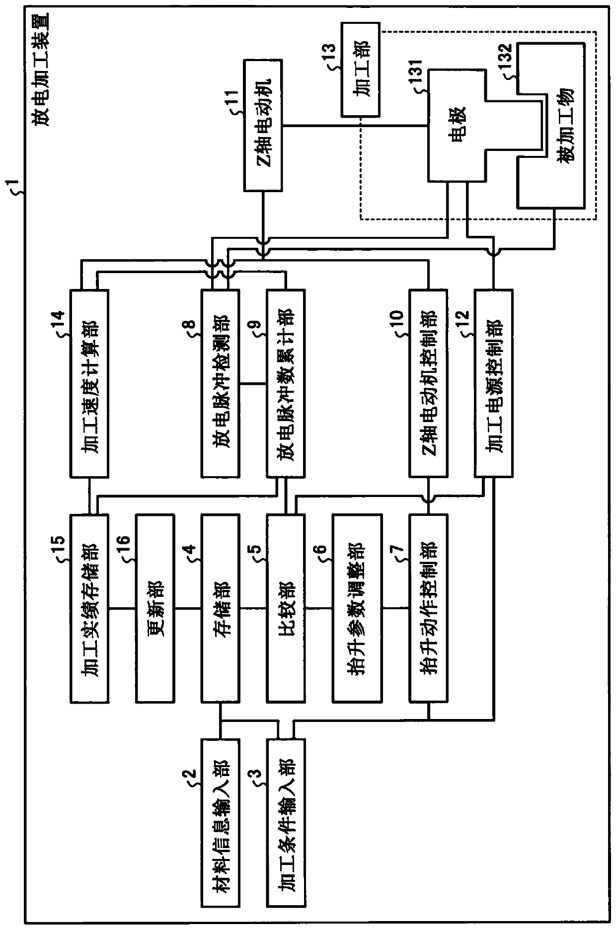
[0022] figure 1 It is a block diagram showing a configuration example of the electrical discharge machining device 1 according to Embodiment 1 of the present invention. The electrical discharge machining device 1 has a material information input unit 2, a processing condition input unit 3, a storage unit 4, a comparison unit 5, a lifting parameter adjustment unit 6, a lifting action control unit 7, a discharge pulse detection unit 8, a discharge pulse number accumulation unit 9, Z-axis motor control unit 10 , Z-axis motor 11 , machining power supply control unit 12 , machining unit 13 , machining speed calculation unit 14 , machining actual record storage unit 15 and update unit 16 . The processing part 13 has: the electrode 131 used for electric discharge machining, and the workpiece 132 which becomes the processing object of electric discharge machining.

[0023] The material information input unit 2 receives input of information on the material of the electrode 131 and inf...

Embodiment approach 2

[0068] In Embodiment 1, the electric discharge machining device 1 stores the optimum value determined according to the combination of the electrode material and the workpiece material, and updates the optimum value appropriately in order to maximize the machining efficiency. However, the optimum value is affected by the processing area, processing conditions, etc. in addition to the combination of the electrode material and the material of the workpiece. In Embodiment 2, the electrical discharge machining device stores optimum values ​​determined according to combinations of electrode materials and workpiece materials, machining areas, and machining conditions, and appropriately updates the optimum values ​​in order to maximize machining efficiency. Differences from Embodiment 1 will be described.

[0069] Image 6 It is a block diagram showing a configuration example of the electrical discharge machining device 1 a according to the second embodiment. Electrical discharge ma...


PUM


Abstract

The present invention is provided with: a material information input unit (2) for receiving input of information about an electrode material and a workpiece material; a machining condition input unit(3) for receiving input of a machining condition for electrical discharge machining; a discharge pulse detection unit (8) for detecting discharge pulses generated during electrical discharge machining; a discharge pulse number integration unit (9) for calculating the number of discharge pulses and calculating an integrated value of discharge pulses per unit time; a jump operation control unit (7)for controlling a jump operation of an electrode (131) included in the machining condition, on the basis of a jump condition for the jump operation; a storage unit (4) for storing a suitable value ofthe discharge pulse number per unit time during electrical discharge machining, the suitable value being determined from a combination of the electrode material and the workpiece material; a comparison unit (5) for comparing the suitable value and the integrated value; and a jump parameter adjustment unit (6) for adjusting the jump condition on the basis of the result of comparison of the suitablevalue and the integrated value. The jump operation control unit (7) controls the jump operation according to the content adjusted by the jump parameter adjustment unit (6).

Description

technical field [0001] The present invention relates to an electric discharge machining device for electric discharge machining and a lifting action control method. Background technique [0002] In an electric discharge machining device for engraving electric discharge machining, if the number of discharge pulses per unit time deviates from the optimum range, that is, the so-called optimum value, the machining speed will decrease and efficient electric discharge machining will not be performed. In order for the electrical discharge machining device to efficiently perform electrical discharge machining, it is necessary to secure an optimum value for the number of electrical discharge pulses. The number of discharge pulses is affected by the concentration of machining chips deposited in the machining gap between the electrode filled with machining fluid and the workpiece. In the electrical discharge machining device, when the concentration of machining chips is too high, it i...

Claims


Application Information

Patent Timeline
IPC IPC(8): B23H7/20B23H1/02B23H7/14
CPCB23H7/20B23H1/02
Inventor 吉川宽史中川孝幸森田一成黑川聪昭
Owner MITSUBISHI ELECTRIC CORP
Learn More