
Assembling type composite floor slab with height limiting device and production process for assembling type composite floor slab

A technology for stacking floor slabs and a production process, applied in the field of construction, can solve the problems of wasting concrete, difficult to determine the pouring height, and difficulty in demoulding the stacking floor slabs, and achieves the effect of reducing the difficulty of demoulding

Pending Publication Date: 2019-12-27
GANSU CONSTR TECH RES & DEV CO LTD
View PDF7 Cites 7 Cited by
  • Summary
  • Abstract
  • Description
  • Claims
  • Application Information

AI Technical Summary

Problems solved by technology

[0004] The invention provides a prefabricated laminated floor slab with a height-limiting device, aiming to solve the problem in the prior art that the pouring height is difficult to determine when pouring concrete on the top of the laminated floor slab, which easily causes waste of concrete
[0005] In addition, another purpose of the present invention is to solve the problem that the existing laminated floor slabs are difficult to demould during production

Method used


Image

  • Assembling type composite floor slab with height limiting device and production process for assembling type composite floor slab
  • Assembling type composite floor slab with height limiting device and production process for assembling type composite floor slab
  • Assembling type composite floor slab with height limiting device and production process for assembling type composite floor slab

Examples


Embodiment Construction

[0035] The present invention will be further described below in conjunction with accompanying drawing:

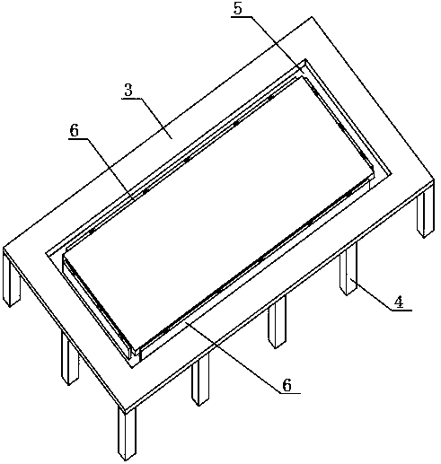
[0036] Such as figure 1 and 2 As shown, a prefabricated laminated floor slab with a height-limiting device has transverse steel bars 10 and longitudinal steel bars 11 poured into the laminated floor, truss steel bars 1 are poured and fixed on the laminated floor, and several vertical steel bars 1 are fixed on the laminated floor. The height-limited columns 2 are all equal in height and their tops are higher than the truss reinforcement 1. The material of the height-limiting column 2 is a steel bar with a diameter of 6-12mm, and the transverse steel bar 10, the longitudinal steel bar 11 and the truss steel bar 1 are all made of Q235 material.

[0037] The production process of the above-mentioned prefabricated laminated floor slab with height limiting device is as follows:

[0038] a. Mold table cleaning. Move the mold table 3 to the cleaning machine of the PC production...


PUM


Abstract

The invention discloses an assembling type composite floor slab with a height limiting device and a production process for the assembling type composite floor slab. Transverse steel bars and longitudinal steel bars are poured in the composite floor slab, truss steel bars are poured on the composite floor slab, the composite floor slab is further fixedly provided with a plurality of vertical heightlimiting columns, and the top ends of the height limiting columns are higher than the truss steel bars. A mold for producing the composite floor slab adopts a structure for facilitating demolding, and the detailed structure is as follows: a mold table is provided with a rectangular opening groove, and a supporting plate is hinged clinging to the inner wall of the opening groove. When side platesare installed, supporting plates are rotated to a horizontal position and are fixed, the supporting plates are rotated to a vertical state to enable the side plates to be suspended after the pouring is finished, and then the side plates are knocked downwards, so that a relatively large shearing force can be generated between the side plates and concrete, and the side plates can be accelerated to be separated from the concrete. The height limiting columns are integrally installed while the composite floor slab manufactured, the height limiting columns can be used for indicating a pouring thickness of the cast-in-place concrete, and the problem of waste caused by excessive pouring of the concrete is effectively solved.

Description

technical field [0001] The invention belongs to the technical field of buildings, and in particular relates to an assembled laminated floor slab with a height limiting device and a production process thereof. Background technique [0002] The laminated floor is a structure that combines prefabricated and cast-in-place concrete better. The bottom plate of the laminated floor and the upper cast-in-place concrete layer are combined to form a whole and work together. During construction, the laminated floor slab is used as the bottom form of the cast-in-place concrete layer, so that it is unnecessary to support the formwork for the cast-in-place layer, reducing the construction process. Since the bottom surface of the laminated floor is smooth and flat, the ceiling does not need to be plastered after the joints are treated, which can further reduce the construction process. This kind of laminated slab has the advantages of high integrity, high rigidity, good crack resistance, l...

Claims


Application Information

Patent Timeline
IPC IPC(8): E04B5/17E04G21/02E04G19/00
CPCE04B5/17E04G19/00E04G21/02
Inventor 冯力强牛昌林魏宏亮王建平吴星蓉张雷胡海涛李强
Owner GANSU CONSTR TECH RES & DEV CO LTD
Learn More