
Self-defoaming microbial sewage treatment tank

A sewage treatment tank, microbial technology, applied in the direction of sustainable biological treatment, aerobic process treatment, foam dispersion/prevention, etc., can solve the problems of destroying the ecological environment of bacterial flora, high cost, foam coverage, etc., and achieve good defoaming effect , wide range of defoaming, and the effect of improving efficiency

Active Publication Date: 2019-12-27
BEIJING HUAMING GUANGYUAN ENVIRONMENT TECH
View PDF6 Cites 6 Cited by
  • Summary
  • Abstract
  • Description
  • Claims
  • Application Information

AI Technical Summary

Problems solved by technology

[0003] There is a common problem in aeration tanks: the surface is covered with a lot of foam
The foam inside is generally divided into chemical foam and biological foam. These foams will cause oxygen to be unable to be transmitted in time, greatly reducing the oxygenation capacity of the water body.
In the prior art, in order to solve this problem, one is to put defoamer into the water body, and the defoamer is easy to affect the water quality and destroy the ecological environment of the flora; Foaming, this defoaming method not only requires the laying of high-cost equipment, but also the high-frequency vibration of the pump during work causes mechanical stress in the connecting pipes, which will damage the dense activated sludge flocs in the microbial flora, from The proliferation of surface-active proteobacteria and filamentous bacteria released from damaged cells will also produce a lot of foam, so the effect of defoaming by pumping water and spraying water is not ideal

Method used


Image

  • Self-defoaming microbial sewage treatment tank
  • Self-defoaming microbial sewage treatment tank
  • Self-defoaming microbial sewage treatment tank

Examples


Embodiment Construction

[0022] The following will clearly and completely describe the technical solutions in the embodiments of the present invention with reference to the accompanying drawings in the embodiments of the present invention. Obviously, the described embodiments are only some, not all, embodiments of the present invention.

[0023] In describing the present invention, it should be understood that the terms "upper", "lower", "front", "rear", "left", "right", "top", "bottom", "inner", " The orientation or positional relationship indicated by "outside", etc. is based on the orientation or positional relationship shown in the drawings, and is only for the convenience of describing the present invention and simplifying the description, rather than indicating or implying that the referred device or element must have a specific orientation, so as to Specific orientation configurations and operations, therefore, are not to be construed as limitations on the invention.

[0024] refer to Figure ...


PUM


Abstract

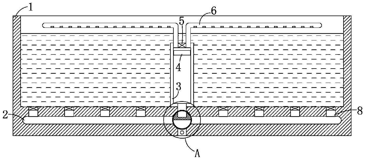
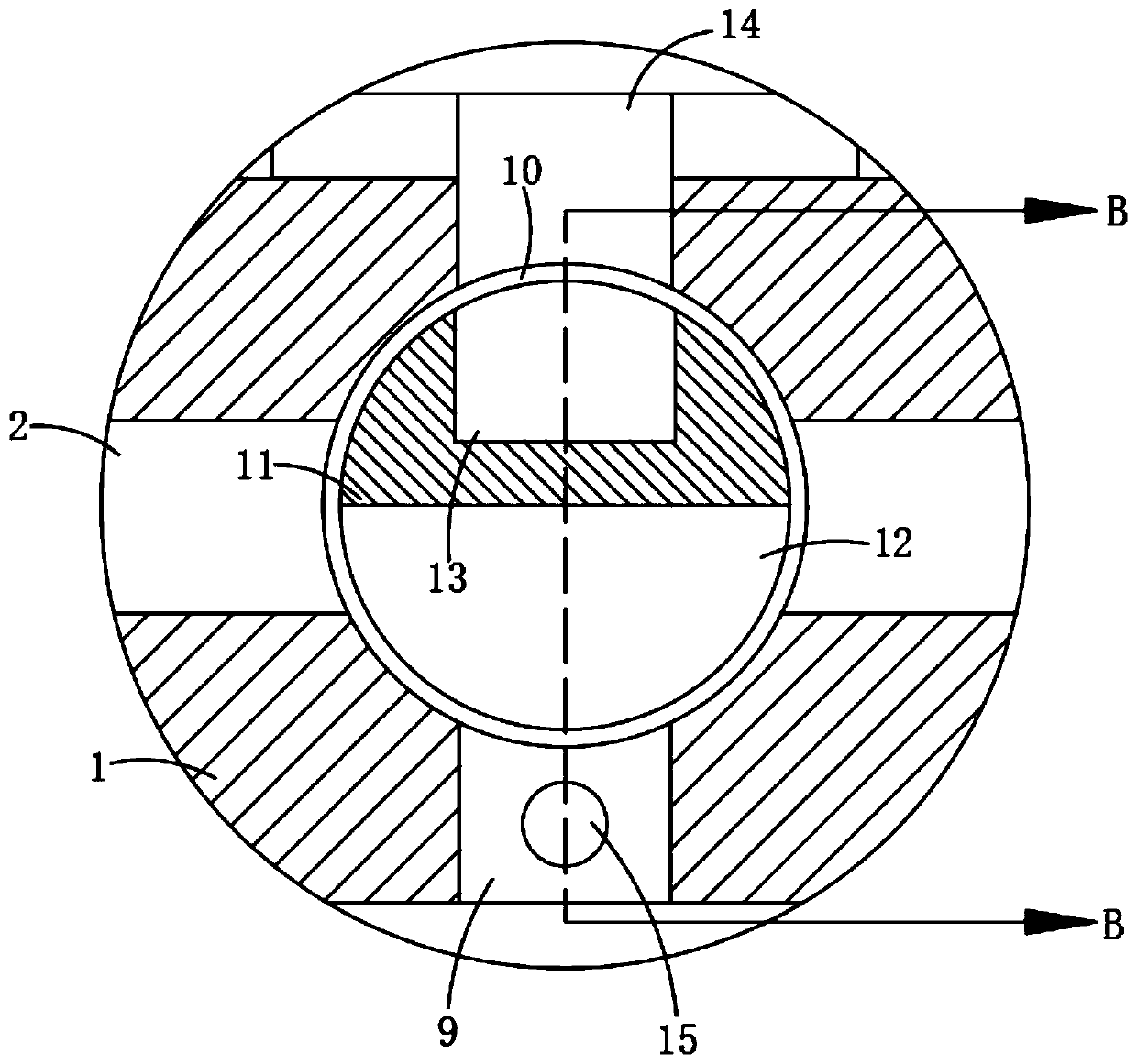
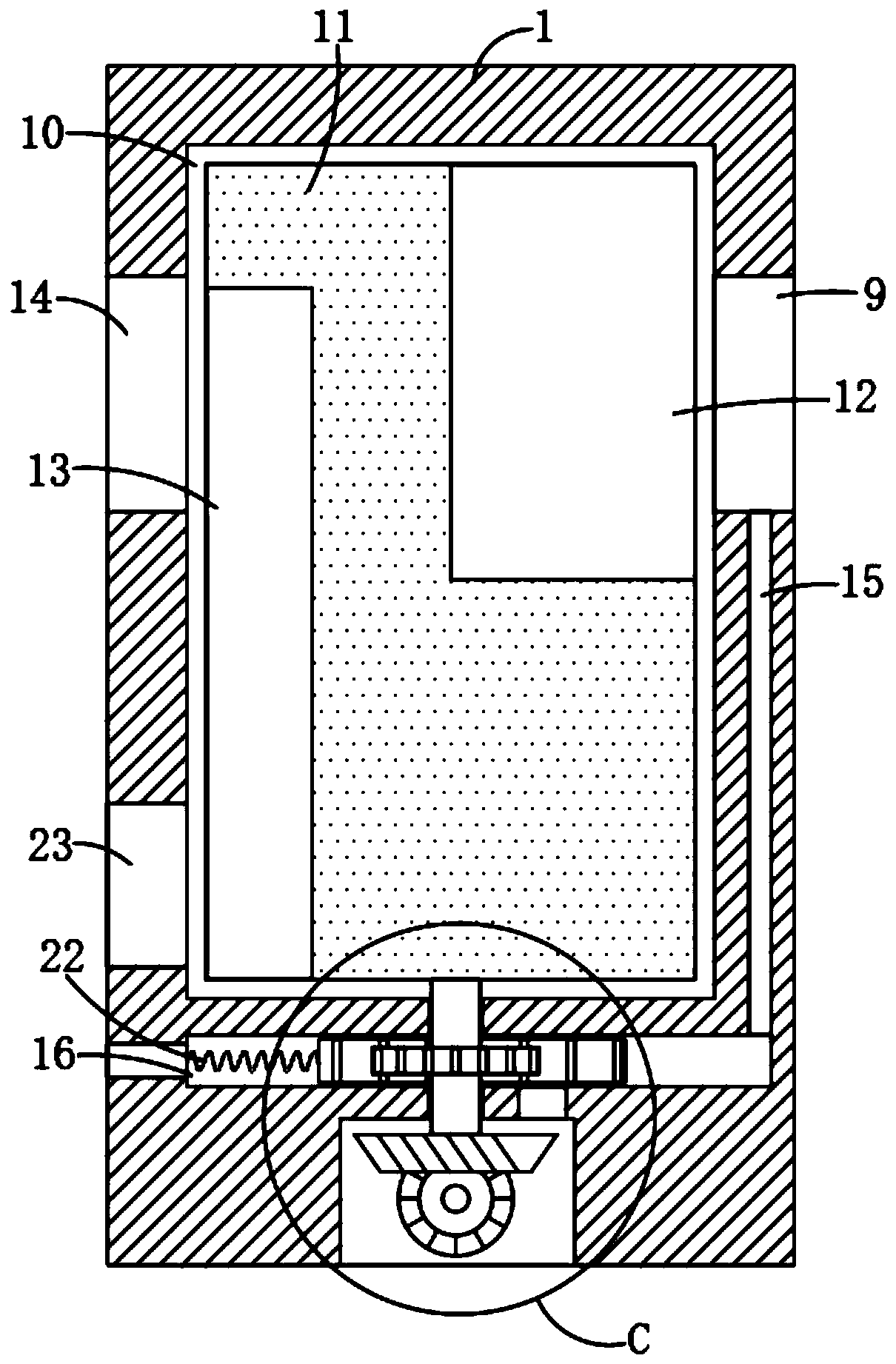
The invention discloses a self-defoaming type microbial sewage treatment tank. The tank comprises a tank body, wherein an aeration pipe is embedded into the inner bottom of the tank body; a pluralityof air outlet holes communicated with the aeration pipe are formed in the side wall of the tank body; a first one-way valve is installed in a gas outlet hole; a stainless steel pipe is rotatably connected to the inner bottom of the tank body; a sliding block is slidably connected to the inner wall of the stainless steel pipe in a sealed mode; a water inlet is formed in the upper end of the stainless steel pipe; and a second one-way valve is installed in the water inlet. According to the treatment tank, high-speed high-pressure gas is introduced into the gas inlet hole to push the sliding blockto move upwards, then water flowing into the stainless steel pipe from the water inlet can be sprayed out through the spraying pipe and sprayed on the water surface, so that water spraying defoamingcan be carried out, complex equipment does not need to be laid, meanwhile, the sliding block is pushed by gas to move upwards in the stainless steel pipe to spray water, high-frequency vibration generated when the water pump works cannot be generated, a large amount of foam cannot be generated, and the defoaming effect is good.

Description

technical field [0001] The invention relates to the technical field of microbial sewage treatment equipment, in particular to a self-defoaming microbial sewage treatment pool. Background technique [0002] Microbial sewage treatment methods can be divided into two categories: anaerobic biological treatment and aerobic biological treatment according to the demand for oxygen. Among them, the aerobic biological treatment method needs to set up an aeration system in the sewage treatment tank to provide oxygen to the aerobic microbial flora in the tank to promote the decomposition of aerobic microorganisms. [0003] There is a common problem in aeration tanks: the surface is covered with a lot of foam. The foam inside is generally divided into chemical foam and biological foam. These foams will cause oxygen to be unable to be transmitted in time, greatly reducing the oxygenation capacity of the water body. In the prior art, in order to solve this problem, one is to put defoamer...

Claims


Application Information

Patent Timeline
IPC IPC(8): C02F3/02B01D19/02
CPCC02F3/02B01D19/02Y02W10/10
Inventor 肖琪琪
Owner BEIJING HUAMING GUANGYUAN ENVIRONMENT TECH
Learn More