A soil tunnel support structure crossing an existing railway and its construction method

A technology of support structure and construction method, applied in tunnels, earthwork drilling, tunnel lining and other directions, can solve the problems of slow construction progress, cumbersome procedures and low construction efficiency.

Active Publication Date: 2021-06-04
XI'AN UNIVERSITY OF ARCHITECTURE AND TECHNOLOGY
View PDF7 Cites 0 Cited by
  • Summary
  • Abstract
  • Description
  • Claims
  • Application Information

AI Technical Summary

Problems solved by technology

[0002] At present, pipe jacking is mostly used in the construction of tunnels crossing existing railways. It is necessary to dig originating shafts and receiving shafts, set up reaction walls, and then use jacks to jack pipes section by section. However, there are positioning deviations in traditional pipe jacking construction. , and it is difficult to adjust the positioning deviation. In addition, the friction force of the traditional jacking method has a large loss of jacking thrust, and the construction efficiency is low. Therefore, the traditional pipe jacking construction method is also relatively cumbersome and its construction progress is slow

Method used


Image

  • A soil tunnel support structure crossing an existing railway and its construction method
  • A soil tunnel support structure crossing an existing railway and its construction method
  • A soil tunnel support structure crossing an existing railway and its construction method

Examples


Embodiment 1

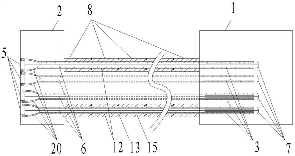
[0063] see figure 1 , a support structure for an earth tunnel passing through an existing railway, comprising a starting shaft 1 and a receiving shaft 2, a supporting pipeline 15 is arranged between the starting shaft 1 and the receiving shaft 2, and the supporting pipeline 15 A positioning conduit 3 passes through the pipe section hole 12 reserved above; one end of the positioning conduit 3 is located in the starting well 1 , and the other end of the positioning conduit 3 is located in the receiving well 2 .

[0064] see figure 1 , a kind of soil tunnel support structure construction method that crosses existing railway, comprises the following steps:

[0065] Step 1: Preparatory work for construction, including:

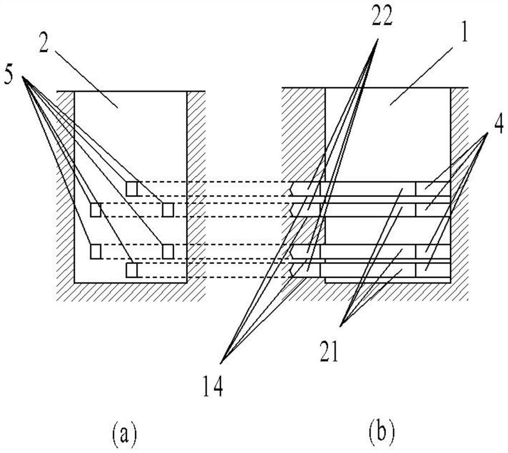
[0066] 1.1. Select areas on both sides of the existing railway, and construct the originating shaft 1 and the receiving shaft 2;

[0067] 1.2. Set up several winches 5 on the well wall of the receiving shaft 2 away from the originating shaft 1, and set the drill...

Embodiment 2

[0108] see figure 1 , a support structure for an earth tunnel passing through an existing railway, comprising a starting shaft 1 and a receiving shaft 2, a supporting pipeline 15 is arranged between the starting shaft 1 and the receiving shaft 2, and the supporting pipeline 15 A positioning conduit 3 passes through the pipe section hole 12 reserved above; one end of the positioning conduit 3 is located in the starting well 1 , and the other end of the positioning conduit 3 is located in the receiving well 2 .

[0109] see figure 1 , a kind of soil tunnel support structure construction method that crosses existing railway, comprises the following steps:

[0110] Step 1: Preparatory work for construction, including:

[0111] 1.1. Select areas on both sides of the existing railway, and construct the originating shaft 1 and the receiving shaft 2;

[0112] 1.2. Set up several winches 5 on the well wall of the receiving shaft 2 away from the originating shaft 1, and set the drill...


PUM


Abstract

A support structure and construction method for an earth tunnel passing through an existing railway. Firstly, a conduit tunnel is obtained by drilling, and a positioning conduit is arranged in the conduit tunnel, and then the other end of a cable connected to a winch is inserted into the positioning conduit. Passing through, the cable passes through one end of the positioning guide and the other end passes out; after the cable passes through the positioning guide, it passes through one end of the cutter head hole and the other end passes out; after the cable passes through the other end of the cutter head hole Connected with the barb, the winch retracts the cable and pulls the cutter head into the soil; when the barb moves to the end along the gap of the gap guide, pull the barb along the gap to remove the barb, and then let the other end of the cable go from the first One end of a pipe section hole goes in and the other end goes out, and then connects with the barb. The winch retracts the cable and pulls the first pipe section monomer into the soil, and repeats the above steps until the supporting structure is completed; the invention can reduce the construction cost. The direction deviation generated when supporting the structure improves the construction speed; it has the characteristics of simplicity and efficiency.

Description

technical field [0001] The invention belongs to the technical field of tunnel construction, and in particular relates to an earth tunnel support structure passing through an existing railway and a construction method thereof. Background technique [0002] At present, pipe jacking is mostly used in the construction of tunnels crossing existing railways. It is necessary to dig originating shafts and receiving shafts, set up reaction walls, and then use jacks to jack pipes section by section. However, there are positioning deviations in traditional pipe jacking construction. , and it is difficult to adjust the positioning deviation. In addition, the friction force of the traditional jacking method has a large loss of jacking thrust, and the construction efficiency is low. Therefore, the traditional pipe jacking construction method is also relatively cumbersome and its construction progress is slow. Contents of the invention [0003] In order to overcome the deficiencies in th...

Claims


Application Information

Patent Timeline
Patent Type & Authority Patents(China)
IPC IPC(8): E21D11/08E21D11/40E21D11/38E21D9/08
CPCE21D9/0607E21D9/08E21D11/08E21D11/38E21D11/40
Inventor 张玉伟肖珂辉宋战平范胜元田小旭周冠南毛建超
Owner XI'AN UNIVERSITY OF ARCHITECTURE AND TECHNOLOGY
Why Eureka
Try Eureka