
A method and device for detecting the position of a motor rotor, and a computer storage medium

A technology of motor rotor and detection method, which is applied to control electromechanical transmission device, control generator, motor generator control, etc. Vibration problem, the effect of improving steady-state characteristics

Active Publication Date: 2021-12-28
GUANGDONG MIDEA WHITE HOME APPLIANCE TECH INNOVATION CENT CO LTD +1
View PDF0 Cites 0 Cited by
  • Summary
  • Abstract
  • Description
  • Claims
  • Application Information

AI Technical Summary

Problems solved by technology

Since the sign function or saturation function is used as the approach rate of the sliding mode surface, there must be a chattering phenomenon, and it is usually necessary to perform low-pass filtering and phase compensation on the opposite potential observations, which complicates the system design and reduces the performance of the observer , which in turn affects the control performance of the motor

Method used


Image

  • A method and device for detecting the position of a motor rotor, and a computer storage medium
  • A method and device for detecting the position of a motor rotor, and a computer storage medium
  • A method and device for detecting the position of a motor rotor, and a computer storage medium

Examples


Embodiment Construction

[0029] The technical solutions in the embodiments of the present application will be clearly and completely described below in conjunction with the drawings in the embodiments of the present application. It should be understood that the specific embodiments described here are only used to explain the present application, but not to limit the present application. In addition, it should be noted that, for the convenience of description, only some structures related to the present application are shown in the drawings but not all structures. Based on the embodiments in this application, all other embodiments obtained by persons of ordinary skill in the art without creative efforts fall within the protection scope of this application.

[0030] The terms "first", "second", etc. in this application are used to distinguish different objects, not to describe a specific order. Furthermore, the terms "include" and "have", as well as any variations thereof, are intended to cover a non-e...


PUM


Abstract

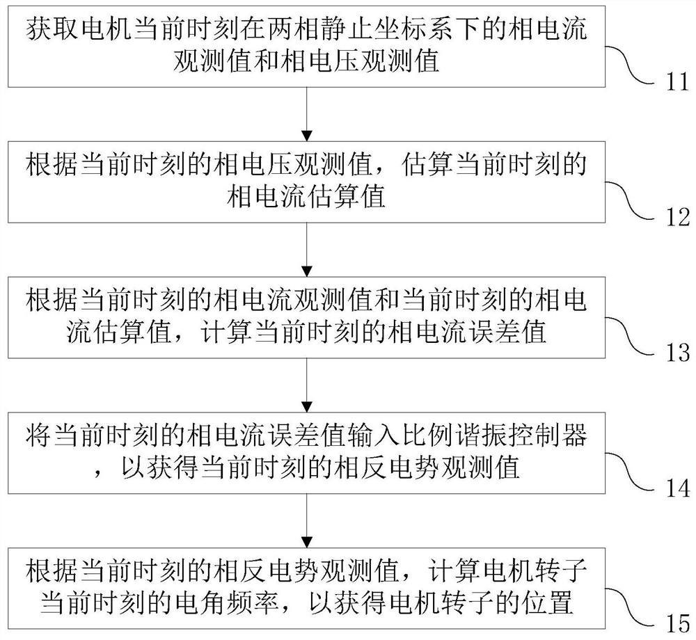
The present application discloses a detection method and device for the rotor position of a motor, and a computer storage medium. The detection method includes: obtaining the phase current observation value and the phase voltage observation value of the motor at the current moment in the two-phase stationary coordinate system; Phase voltage observation value, estimate the phase current estimation value at the current moment; calculate the phase current error value at the current moment according to the phase current observation value at the current moment and the phase current estimation value at the current moment; input the phase current error value at the current moment into the ratio The resonance controller is used to obtain the observed value of the opposite potential at the current moment; according to the observed value of the opposite potential at the current moment, the electrical angular frequency of the motor rotor at the current moment is calculated to obtain the position of the motor rotor. Through the above method, the adaptive resonance control is used as the approach rate of the sliding mode observer, which avoids the adverse effects of chattering in the traditional method, and also eliminates the additional low-pass filter and its phase compensation link, which improves the observation accuracy and steady state performance.

Description

technical field [0001] The present application relates to the technical field of motors, in particular to a method and device for detecting the position of a motor rotor, and a computer storage medium. Background technique [0002] The permanent magnet synchronous motor (PMSM) has the advantages of light weight, small size and high operating efficiency, and is widely used in the fields of household appliances and industrial automation. The traditional motor drive system needs to detect the rotor position of the motor through a position sensor, which not only increases the cost, but also reduces the reliability of the system. [0003] In recent years, the position sensorless control technology suitable for permanent magnet synchronous motors has developed rapidly, and how to accurately measure the rotor position of the motor has become an urgent problem to be solved. [0004] The sliding mode observer is a commonly used motor rotor position detection method. The phase curren...

Claims


Application Information

Patent Timeline
Patent Type & Authority Patents(China)
IPC IPC(8): H02P21/13H02P21/14H02P21/18H02P21/22H02P25/022
CPCH02P21/0007H02P21/13H02P21/14H02P21/18
Inventor 林环城刘毅
Owner GUANGDONG MIDEA WHITE HOME APPLIANCE TECH INNOVATION CENT CO LTD
Learn More