Mechanical overload switch for external ballistic trajectory data acquisition system

A technology of data acquisition system and overload switch, which is applied in the direction of electric switch, ammunition test, ammunition, etc. It can solve the problems of short connection time between moving contact and static contact, inability to guarantee power supply circuit, spring deformation, etc.

Pending Publication Date: 2019-12-20
NANJING UNIV OF SCI & TECH
View PDF1 Cites 0 Cited by
  • Summary
  • Abstract
  • Description
  • Claims
  • Application Information

AI Technical Summary

Problems solved by technology

[0003] In the prior art, the patent document with the publication number "CN201549441U" discloses a mechanical acceleration switch without power supply, including a housing, a base, a bracket, a damper, a static contact and an inertial mass movement system, wherein the inertial mass The movable system is composed of a mass unit, a spring unit and a damper. The mass unit is composed of a positioning ring, an upper mass block, a lower mass block and a moving contact. The spring unit is composed of a spring leaf and a precision compression spring. , using the inertial mass activity system to feel the acceleration and generate an inertial force proportional to the acceleration, causing the spring to deform. When the movable contact moves to the static contact with the inertial mass activity system, the acceleration switch outputs a conduction signal, but this structure The disadvantage is that the moving contact and the static contact will be separated immediately after they are combined, resulting in a too short conduction time for the connection between the moving contact and the static contact
If the time is too short, it cannot guarantee that the power supply circuit will power on the missile sensor after the overload shock completely disappears.

Method used


Image

  • Mechanical overload switch for external ballistic trajectory data acquisition system
  • Mechanical overload switch for external ballistic trajectory data acquisition system
  • Mechanical overload switch for external ballistic trajectory data acquisition system

Examples


Embodiment Construction

[0016] The present invention will be further introduced below in conjunction with the accompanying drawings and specific embodiments.

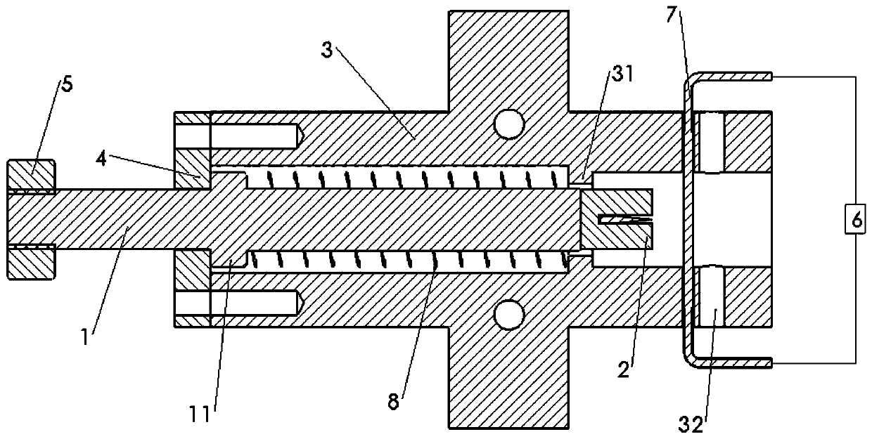
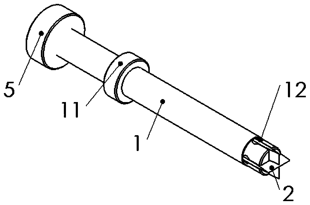
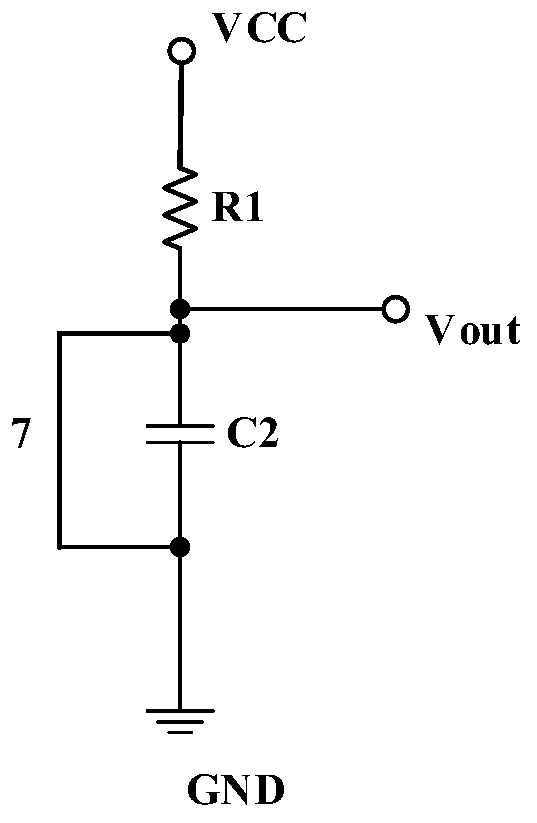
[0017] A mechanical overload switch for an external ballistic data acquisition system of the present invention includes an excitation component, a switch housing 3, a housing cover 4, a return spring 8, a delay circuit 6, and a wire 7; the excitation component includes a mass block 5 , trigger rod 1, contact 2; the trigger rod 1 is a cylindrical structure with a shoulder 11 in the middle of the cylinder for supporting one end of the return spring 8; a ring of bosses 31 are provided in the switch housing 3 for Support the other end of the return spring 8; one end of the excitation rod 1 is located inside the switch housing 3, and the other end is located outside the switch housing 3, the switch housing 3 is provided with a housing cover 4, and the activation rod 1 passes through the housing cover 4, The housing cover 4 axially locates the shaft...


PUM


Abstract

A mechanical overload switch for an external ballistic trajectory data acquisition system comprises an excitation part, a switch shell, a shell sealing cover, a reset spring, a time delay circuit anda wire. The excitation part comprises a mass block, an excitation rod and a contact; the excitation rod is of a cylindrical structure, and a shaft shoulder is arranged in the middle of a cylinder andused for supporting one end of the reset spring. A boss circle is arranged in the switch shell; one end of the excitation rod is located inside the switch shell, and the other end is located outside the switch shell; the shell sealing cover is arranged on the switch shell, and the excitation rod penetrates through the shell sealing cover. The reset spring is sleeved on the excitation rod and is positioned in the switch shell; the contact is fixed at one end of the excitation rod and is located inside the switch shell; the mass block is fixed at the other end of the excitation rod and located outside the switch shell; the wire penetrates through the switch shell and is opposite to the contact; the wire is connected in parallel with the delay circuit; and a tensioning mechanism is arranged between the wire and the switch shell. According to the invention, the acceleration in the overload impact process can be utilized to enable the power supply circuit to power on a missile-borne sensorafter the overload impact disappears.

Description

technical field [0001] The invention belongs to the field of external ballistic data collection and control, in particular to a mechanical overload switch used in the external ballistic data collection system. Background technique [0002] Smart ammunition obtains its own angular velocity, acceleration and other sensor data, calculates its own attitude and position information, and sends it to the control system to realize functions such as extended range and precise strike. In the R&D and testing phase, it is necessary to collect the external ballistic sensor data and calculation data of the smart ammunition. Usually, the sensor in the power-on state is difficult to withstand the environment of high overload impact, and the internal structure of the sensor is easily damaged or cannot work normally. If the sensor is powered on before the overload test, the performance of the live sensor after experiencing a high overload impact will not be guaranteed. Powering on after an ...

Claims


Application Information

Patent Timeline
Patent Type & Authority Applications(China)
IPC IPC(8): H01H35/14F42B35/02
CPCF42B35/02H01H35/14H01H35/141
Inventor 王宇朱立华吴志强刘辰
Owner NANJING UNIV OF SCI & TECH
Why Eureka
Try Eureka