
Fiber bragg grating clinometer

A fiber grating and inclinometer technology, which is applied in the field of sensing, can solve the problems of low accuracy, large size and short life of the sensor, and achieve the effects of high measurement accuracy, large measurement range and simple structure

Inactive Publication Date: 2019-12-20
SHIJIAZHUANG TIEDAO UNIV
View PDF0 Cites 3 Cited by
  • Summary
  • Abstract
  • Description
  • Claims
  • Application Information

AI Technical Summary

Problems solved by technology

[0004] The purpose of the embodiments of the present invention is to provide a fiber grating inclinometer, which aims to solve the technical problem that the existing fiber grating inclinometer sensor is difficult to be applied to the deformation monitoring of engineering structures due to the shortcomings of low precision, short life, and large volume.

Method used


Image

  • Fiber bragg grating clinometer
  • Fiber bragg grating clinometer
  • Fiber bragg grating clinometer

Examples


Embodiment Construction

[0026] In order to make the technical problems, technical solutions and beneficial effects to be solved by the present invention clearer, the present invention will be further described in detail below in conjunction with the accompanying drawings and embodiments. It should be understood that the specific embodiments described here are only used to explain the present invention, not to limit the present invention.

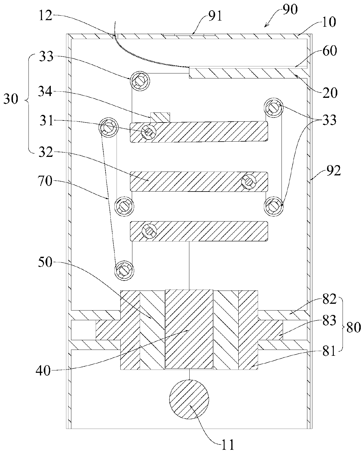
[0027] Please also refer to figure 1 , figure 2 and Figure 4 Now, the fiber grating inclinometer provided by the embodiment of the present invention will be described. The fiber grating inclinometer includes a housing 10 , and an elastic beam 20 , a force amplification component 30 , a first magnet 40 and a second magnet 50 arranged in the housing 10 .

[0028] The elastic beam 20 is located on the upper part of the housing 10 and placed horizontally, one end is connected to the inner wall of the housing 10 , and the other end is a free end. A fiber grating 6...


PUM


Abstract

The invention provides a fiber bragg grating clinometer, and belongs to the field of sensing technology. The fiber bragg grating clinometer comprises a shell, and an elastic beam, a force amplification component, a first magnet and a second magnet, which are disposed in the shell; the elastic beam is located at the upper part of the shell and is placed horizontally, one end of the elastic beam isconnected to an inner wall of the shell, and the other end of the elastic beam is a free end; a fiber bragg grating for monitoring the elongation of the elastic beam is attached to the elastic beam; the force amplification component is located below the elastic beam; the first magnet is located below the first magnet and is connected with the free end of the elastic beam through a rigid wire bypassing the force amplification component; the second magnet is arranged at the outside of the first magnet in a sleeving manner and is in clearance fit with the first magnet; and the second magnet is fixedly arranged in the shell and is magnetically repulsive with the first magnet. The fiber bragg grating clinometer provided by the invention has high measurement accuracy, a large measurement range,a simple structure and convenient use, and is of great significance for the structural deformation monitoring of civil engineering.

Description

technical field [0001] The invention belongs to the technical field of sensing, and more specifically relates to a fiber grating inclinometer. Background technique [0002] The measurement of soil inclination is one of the important indicators of engineering monitoring and engineering safety and stability, so inclinometers are widely used in in-situ monitoring of geotechnical engineering, especially in slopes, roadbeds, soil dams and underground caverns. Chamber deep lateral displacement monitoring. Most of the traditional inclinometer sensors are electronic component sensors, which inevitably bring the shortcomings of being susceptible to electromagnetic radiation interference and poor long-term stability, and cannot meet the needs of use in harsh working environments such as strong electromagnetic radiation. [0003] Fiber Bragg Grating is a kind of strain sensing element with excellent performance. It has the advantages of high sensitivity, small size, corrosion resistan...

Claims


Application Information

Patent Timeline
IPC IPC(8): G01B11/26G01B11/16G01C9/00
CPCG01B11/165G01B11/26G01C9/00
Inventor 张浩钟志鑫段君淼郭志利张雷翟步升王爽王麒麟刘广逊
Owner SHIJIAZHUANG TIEDAO UNIV
Learn More