
An integrated hydraulic control unit

A control unit and integrated technology, applied in the direction of fluid pressure actuation device, fluid pressure actuation system components, servo motor components, etc., can solve the problems of cumbersome component replacement and maintenance, reducing complexity, and large pressure loss along the way. , to improve the system efficiency and response speed, reduce the length of the hydraulic pipeline, and reduce the pressure loss along the way

Active Publication Date: 2021-04-20
AEROSPACE HEAVY IND
View PDF3 Cites 0 Cited by
  • Summary
  • Abstract
  • Description
  • Claims
  • Application Information

AI Technical Summary

Problems solved by technology

[0002] In the hydraulic system design of traditional construction machinery, components are usually arranged according to the direction of the frame, resulting in scattered component layout, intricate pipelines in the vehicle, poor assembly and maintainability, and cumbersome component replacement and maintenance.
At the same time, the decentralized layout leads to long pipelines, large pressure loss along the way, slow response speed, and high energy consumption.
In the prior art, in order to cope with such engineering applications, the centralized arrangement is carried out to the greatest extent according to the specific structural form of the vehicle frame, but it is only a small-scale centralized arrangement, and the system design, assembly and debugging have not substantially reduced the complexity. degree

Method used


Image

  • An integrated hydraulic control unit
  • An integrated hydraulic control unit
  • An integrated hydraulic control unit

Examples


Embodiment Construction

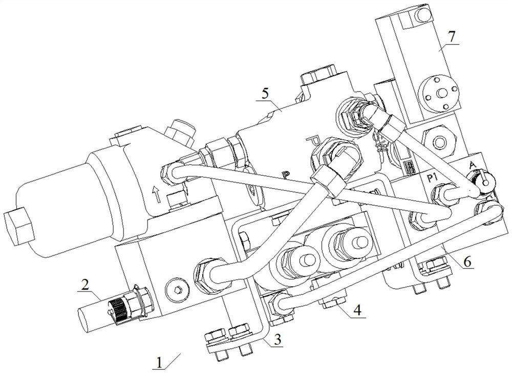
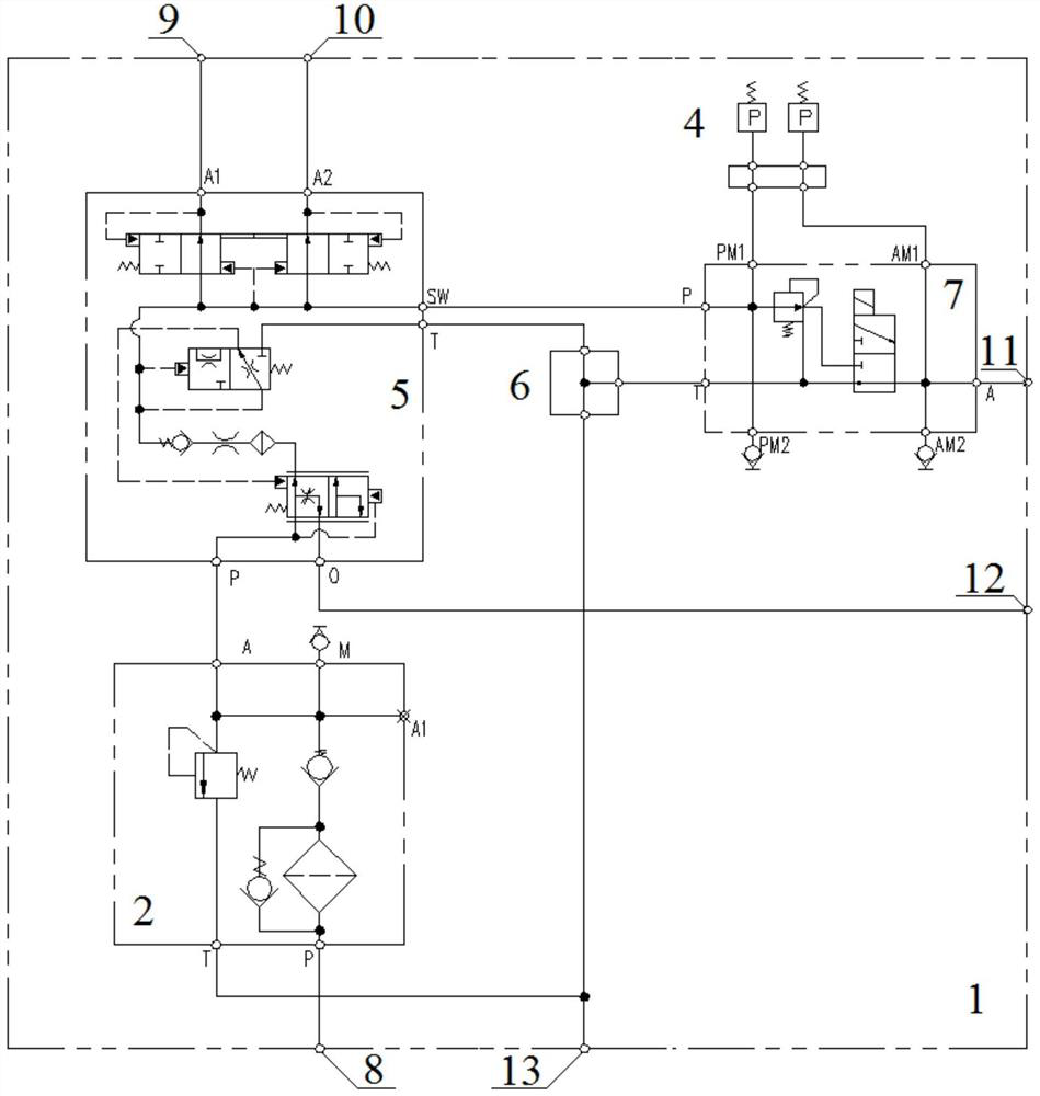
[0043] The embodiments of the present application provide an integrated hydraulic control unit to solve the technical problems of large-scale structure and scattered layout of hydraulic control units in the prior art.

[0044] In order to better understand the above-mentioned technical solution, the above-mentioned technical solution will be described in detail below in conjunction with the accompanying drawings and specific implementation methods. It should be understood that the embodiments of the present invention and the specific features in the embodiments are detailed descriptions of the technical solutions of the present application. , rather than limiting the technical solutions of the present application, the embodiments of the present application and the technical features in the embodiments can be combined without conflict.

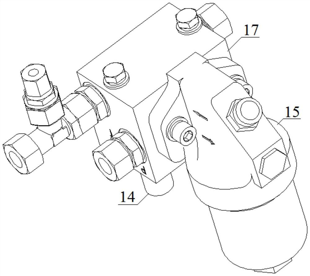
[0045] see figure 1 , figure 2 and Figure 7 , an integrated hydraulic control unit, including: a bracket 3 and a unit oil inlet 8 fixed th...


PUM


Abstract

The invention belongs to the technical field of hydraulic control, and discloses an integrated hydraulic control unit, comprising: a bracket and a unit oil inlet fixed on it, a unit oil return port, a first high-pressure oil port, a second high-pressure oil port, a low-pressure Oil port, constant flow oil port, overflow valve group, liquid charging valve group, pressure reducing valve group, oil return confluence block and sensor assembly; the liquid charging valve group includes: flow valve, first one-way valve, hydraulic control The reversing valve, the first reversing valve and the second reversing valve; the oil inlet of the relief valve group is connected with the unit oil inlet, the oil return port of the relief valve group is connected with the unit oil return port, and the relief valve group The oil outlet of the pressure reducing valve group is connected with the oil inlet of the flow valve; the oil inlet of the pressure reducing valve group is connected with the oil outlet of the first one-way valve, and the oil return port of the pressure reducing valve group is connected with the oil return confluence block; The oil outlet of the valve group is connected with the low-pressure oil port; the oil inlet and the oil outlet of the decompression valve group are respectively connected with the oil return port of the sensor assembly, and the oil outlet of the confluence block is connected with the oil return port of the unit.

Description

technical field [0001] The invention relates to the technical field of hydraulic control, in particular to an integrated hydraulic control unit. Background technique [0002] In the hydraulic system design of traditional construction machinery, components are usually arranged according to the direction of the frame, resulting in scattered component layout, intricate pipelines in the vehicle, poor assembly and maintainability, and cumbersome component replacement and maintenance. At the same time, the decentralized layout leads to long pipelines, large pressure loss along the way, slow response speed, and high energy consumption. In the prior art, in order to cope with such engineering applications, the centralized arrangement is carried out to the maximum extent according to the specific structural form of the frame, but it is only a small-scale centralized arrangement, and the system design, assembly and debugging have not substantially reduced the complexity. degree. Co...

Claims


Application Information

Patent Timeline
Patent Type & Authority Patents(China)
IPC IPC(8): F15B13/02F15B21/041
CPCF15B13/02F15B13/024F15B13/025F15B13/027F15B21/041F15B2013/004
Inventor 杨楠孟峰魏首材张伟郑芳
Owner AEROSPACE HEAVY IND
Learn More