Transportation system and method for blast furnace shell

A blast furnace shell and transportation system technology, which is applied in the field of blast furnace overhaul, can solve the problems of low safety, high construction cost, low stability, etc., and achieves the effects of saving the use of benches, low installation cost, and simple installation.

Inactive Publication Date: 2019-12-20
SHANGHAI BAOYE CONSTR INDAL FURNACE ENG TECH +1
View PDF7 Cites 1 Cited by
  • Summary
  • Abstract
  • Description
  • Claims
  • Application Information

AI Technical Summary

Problems solved by technology

[0004] For this reason, the technical problem to be solved by the present invention is to overcome the problems of low stability, high construction cost and low safety performance in the prior art, thereby providing a blast furnace with high stability, low construction cost and high safety performance Furnace shell transport system and method

Method used


Image

  • Transportation system and method for blast furnace shell
  • Transportation system and method for blast furnace shell
  • Transportation system and method for blast furnace shell

Examples


Embodiment 1

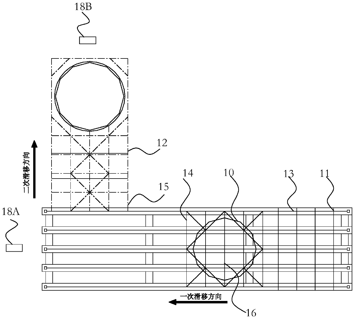
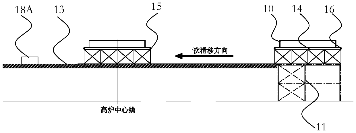
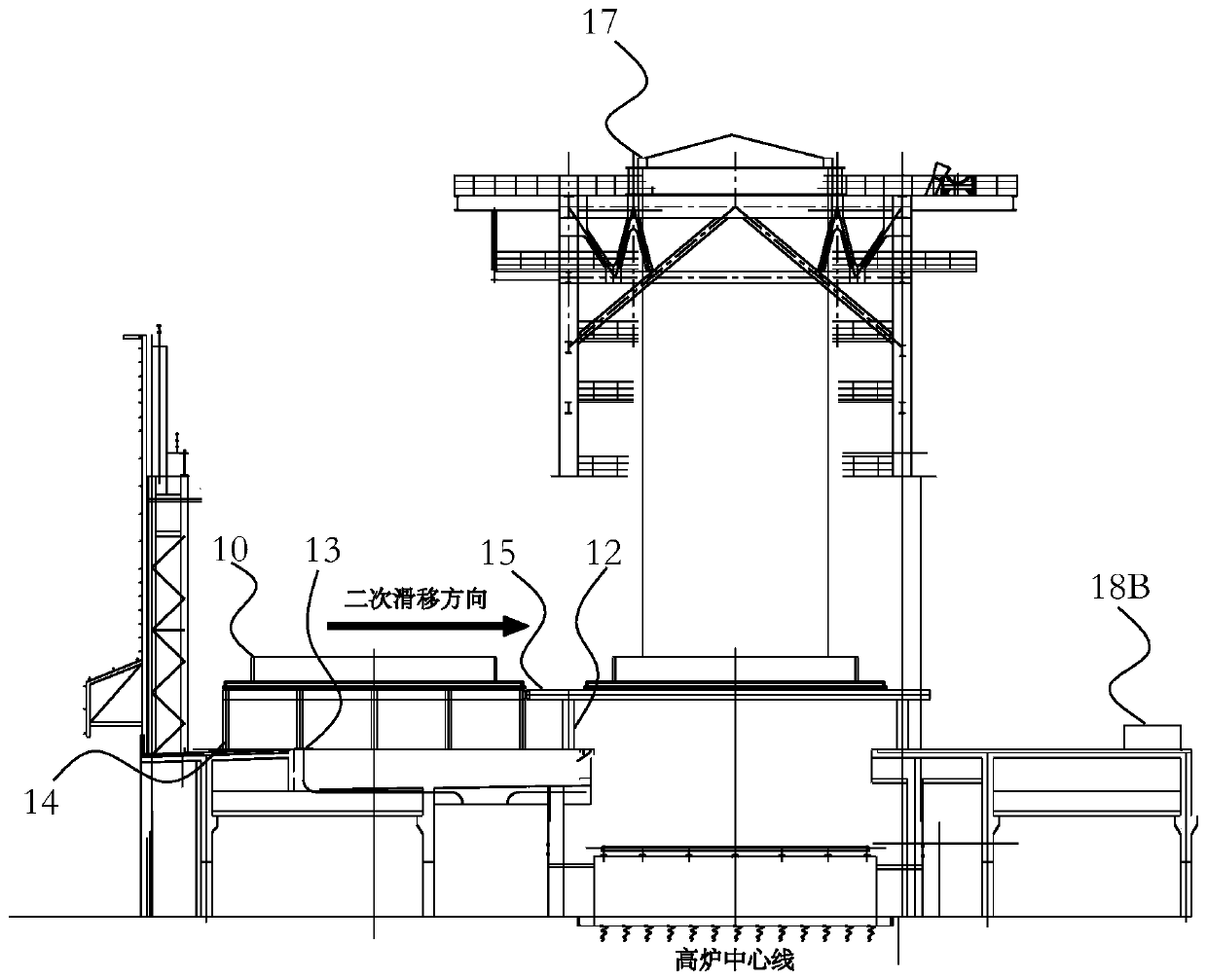
[0023] Such as figure 1 and figure 2 as well as image 3 As shown, this embodiment provides a transportation system for blast furnace shells, including a material receiving platform 11 arranged outside the casthouse and a frame 12 around the furnace body arranged around the center of the casthouse furnace frame, wherein A sliding track 13 is provided on the material receiving platform 11 and the casthouse platform, a sliding truss 14 is arranged on the primary sliding track 13, and a frame 12 around the sliding truss 14 and the furnace body The upper part is provided with a secondary sliding track 15, and the extending direction of the primary sliding track 13 intersects with the extending direction of the secondary sliding track 15, and the sliding truss 14 is provided with a sliding car 16, The skid truck 16 transports the furnace shell 10 from the material receiving platform 11 to an installation position on the secondary skid track 15 via the primary skid track 13 .

...

Embodiment 2

[0029] Such as figure 1 and figure 2 as well as image 3 As shown, this embodiment provides a method for transporting a blast furnace shell, using the blast furnace shell transport system described in Embodiment 1 to transport the furnace shell 10, including the following steps: Step S1: Put the assembled furnace shell 10 Hoisting to the skid car 16 on the skid truss 14 on the material receiving platform 11; step S2: pulling the skid truss 14, sliding the furnace shell 10 to the interface position of the frame 12 around the furnace body, and completing once Sliding; step S3: pulling the skid car 16, sliding the furnace shell from the interface position of the frame 12 around the furnace body to the center of the furnace body frame, transporting it to the installation position, and completing the secondary sliding; step S4: waiting After the furnace shell 10 is lifted and fixed, the trolley 16 is pulled back to the sliding truss 14 at the interface position of the frame 12 a...


PUM


Abstract

The invention relates to a transportation system and method for a blast furnace shell. The transportation system comprises a material receiving platform arranged outside a casting house and a furnacebody surrounding frame arranged at the periphery of the center of a casting house furnace body frame, wherein a primary sliding rail is arranged on the material receiving platform and a casting houseplatform, a sliding truss is arranged on the primary sliding rail, a secondary sliding rail is arranged above the sliding truss and the furnace body surrounding frame, the extending direction of the primary sliding rail is intersected with the extending direction of the secondary sliding rail, a sliding vehicle is arranged on the sliding truss, and the sliding vehicle transports the furnace shellfrom the material receiving platform to the mounting position on the secondary sliding rail through the primary sliding rail. The system and method have the advantages of low construction cost and high safety.

Description

technical field [0001] The invention relates to the technical field of blast furnace overhaul, in particular to a transportation system and method for a blast furnace shell. Background technique [0002] Blast furnace is a widely used iron smelting equipment. Some large blast furnaces have a total weight of several thousand tons, and the roof system on the top is as high as more than 100 meters. , heavy and difficult to construct. [0003] In order to overcome the above problems, the Chinese invention patent (CN109097516A) discloses a construction method for blast furnace overhaul engineering to replace the blast furnace shell, including: dividing the new blast furnace shell into a segmented combined structure, and moving the new blast furnace outside the casting yard Set up the lifting support frame and the pushing trolley on the side; set up the lifting device on the rigid frame of the furnace roof, and remove the upper layers of the furnace body frame platform on the pus...

Claims


Application Information

Patent Timeline
Patent Type & Authority Applications(China)
IPC IPC(8): C21B7/00B65G35/00B66C13/08
CPCC21B7/00B65G35/00B66C13/08F27D1/0043F27D2001/005
Inventor 王雷郭高峰袁金兵
Owner SHANGHAI BAOYE CONSTR INDAL FURNACE ENG TECH
Why Eureka
Try Eureka