Novel chain bucket machine

A chain bucket machine, a new type of technology, applied in the directions of transportation, packaging, loading/unloading, etc., can solve the problems of reducing the stability of the whole machine, increasing the center of gravity of the whole machine, and large radius of gyration, so as to reduce the weight and improve the stability under pressure , the effect of small radius of gyration

Inactive Publication Date: 2019-12-20
NANTONG RAINBOW HEAVY MACHINERIES
View PDF6 Cites 0 Cited by
  • Summary
  • Abstract
  • Description
  • Claims
  • Application Information

AI Technical Summary

Problems solved by technology

[0004] 1. The compression beams such as the balance beam and the counterweight beam are relatively long. In order to meet their overall rigidity and stability, additional weight must be added; this part is at the top of the equipment, and its weight increases the center of gravity of the whole machine. , reducing the stability of the machine
[0005] 2. The counterweight has a large radius of gyration, a large swing range and a large dynamic load during the luffing motion

Method used


Image

  • Novel chain bucket machine
  • Novel chain bucket machine

Examples


Embodiment Construction

[0022] The present invention will be described in further detail below through examples, and the following examples are explanations of the present invention and the present invention is not limited to the following examples.

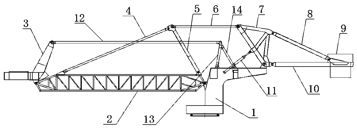
[0023] Such as figure 1 As shown, a new chain bucket machine of the present invention includes an L-shaped column rotating body 1, a boom body 2, a BE hoist 3, a holding rod system, a front rod 4, a swing rod 5, a middle rod 6, and a counterweight tripod 7. Rear pull rod 8, counterweight 9, counterweight beam 10 and hydraulic cylinder 11, one end of boom main body 2 is hinged on L-shaped column rotating body 1, BE hoist 3 is hinged on the other end of boom main body 2, BE The upper end of the hoist 3 is connected to the L-shaped column rotating body 1 through the holding rod system. One end of the swing rod 5 is hinged at one end of the boom body 2, and the other end of the swing rod 5 is respectively hinged with one end of the front tie rod 4 and one ...


PUM


Abstract

The invention discloses a novel chain bucket machine. One end of a boom main machine is hinged onto an L-shaped stand column rotary body; a BE lifter is hinged at the other end of the boom main machine; the upper end of the BE lifter is connected to the L-shaped stand column rotary body through a holding pulling rod system; one end of a swing rod is hinged at one end of the boom main machine, andthe other end of the swing rod is separately hinged with one end of a front pulling rod and one end of a middle puling rod; the other end of the front pulling rod is hinged on the other end of the boom main machine; the other end of the middle pulling rod is hinged with a first corner of a counterweight tripod; a second corner of the counterweight tripod is hinged on the L-shaped stand column rotary body and is hinged with one end of a counterweight beam; a third corner of the counterweight tripod is hinged with one end of a rear pulling rod; a counterweight is arranged at the other end of therear pulling rod and the other end of the counterweight beam, and the other end of the rear pulling rod is mutually connected to the other end of the counterweight beam; and a hydraulic cylinder is hinged on the L-shaped stand column rotary body, and one end of the hydraulic cylinder is hinged on the counterweight tripod. The novel chain bucket machine reduces load, and improves stability.

Description

technical field [0001] The invention relates to a chain bucket machine, in particular to a novel chain bucket machine, which belongs to the field of wharf equipment. Background technique [0002] Chain Bucket Full Chain Bucket Ship Unloader is a bulk material continuous ship unloading machine that uses chain buckets to dig out materials from seagoing cabins and unloads materials to the wharf through the on-board conveyor system. The chain bucket machine of prior art is as figure 2 As shown, its upper balance steel frame is made up of balance beam 21, front tie rod 4, strut bar 22, rear tie rod 8, counterweight beam 10, and each part is connected as a steel frame structure by welding. The upper balance steel frame hangs the BE hoist and the arm frame of the belt conveyor at the front end, and installs the counterweight at the rear end. When the chain bucket ship unloader moves in luffing motion, under the drive of the hydraulic cylinder 11, the entire upper balance steel fr...

Claims


Application Information

Patent Timeline
Patent Type & Authority Applications(China)
IPC IPC(8): B65G67/60
CPCB65G67/606
Inventor 朱显平崔益华杨大海邵海林
Owner NANTONG RAINBOW HEAVY MACHINERIES
Why Eureka
Try Eureka