
A fixing device for electric equipment transportation

A technology for fixing devices and power equipment, applied in transportation and packaging, trolley accessories, multi-axis trolleys, etc., can solve the problems of power equipment damage, power equipment damage, simple structure, etc.

Active Publication Date: 2020-10-27
JINAN CITY CHANGQING DISTRICT POWER SUPPLY CO OF STATE GRID SHANDONG ELECTRIC POWER CO +1
View PDF8 Cites 0 Cited by
  • Summary
  • Abstract
  • Description
  • Claims
  • Application Information

AI Technical Summary

Problems solved by technology

[0002] Power equipment mainly includes power generation equipment and power supply equipment. Power generation equipment is mainly power plant boilers, steam turbines, gas turbines, water turbines, generators and transformers, etc. Power supply equipment is mainly transmission lines of various voltage levels, transformers, contactors, etc. Devices, etc., the power components inside the power equipment are very easy to be damaged during the transportation process due to the shaking of the equipment or collision with the transportation place, resulting in the failure of the normal use of the power equipment, so it is often used during the transportation of power equipment to the fixing device, but the existing fixing device is often relatively simple in structure, and it is difficult to effectively fix the power equipment. Although the existing fixing equipment can fix the power device, it is easy to shake with the transport vehicle, which will not only cause damage to the fixing device, but also cause damage to the power equipment. If it is only mechanically pressurized, it is difficult to achieve the expected effect. If the pressure is too large, it will easily cause damage to the electrical equipment, if the pressure is too small, the fixing effect will not be achieved, and it will also easily cause damage

Method used


Image

  • A fixing device for electric equipment transportation
  • A fixing device for electric equipment transportation
  • A fixing device for electric equipment transportation

Examples


Embodiment Construction

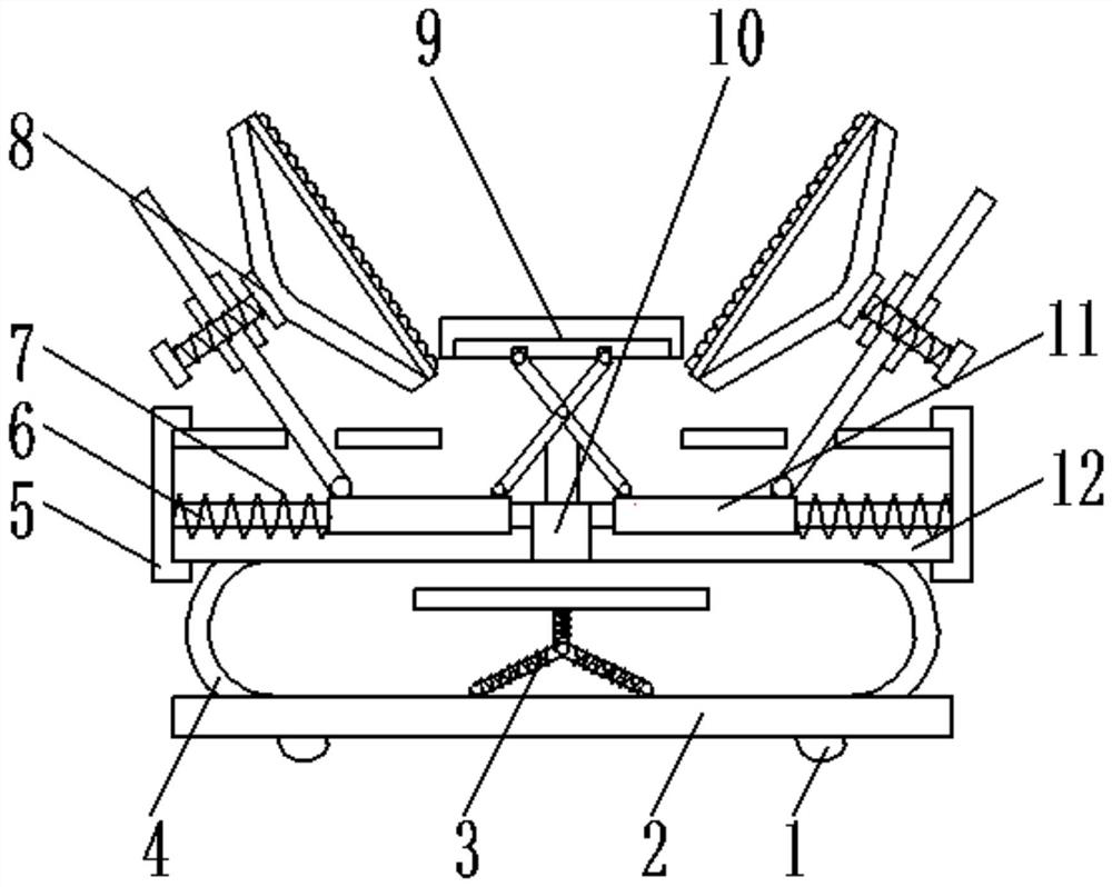
[0034] Attached below Figure 1-8 , clearly and completely describe the technical solutions in the embodiments of the present invention, obviously, the described embodiments are only some of the embodiments of the present invention, not all of them. Based on the embodiments of the present invention, all other embodiments obtained by persons of ordinary skill in the art without making creative efforts belong to the protection scope of the present invention.

[0035] In describing the present invention, it should be understood that the terms "longitudinal", "transverse", "upper", "lower", "front", "rear", "left", "right", "vertical", The orientations or positional relationships indicated by "horizontal", "top", "bottom", "inner", "outer", etc. are based on the orientations or positional relationships shown in the drawings, and are only for the convenience of describing the present invention, rather than indicating or It should not be construed as limiting the invention by implyin...


PUM


Abstract

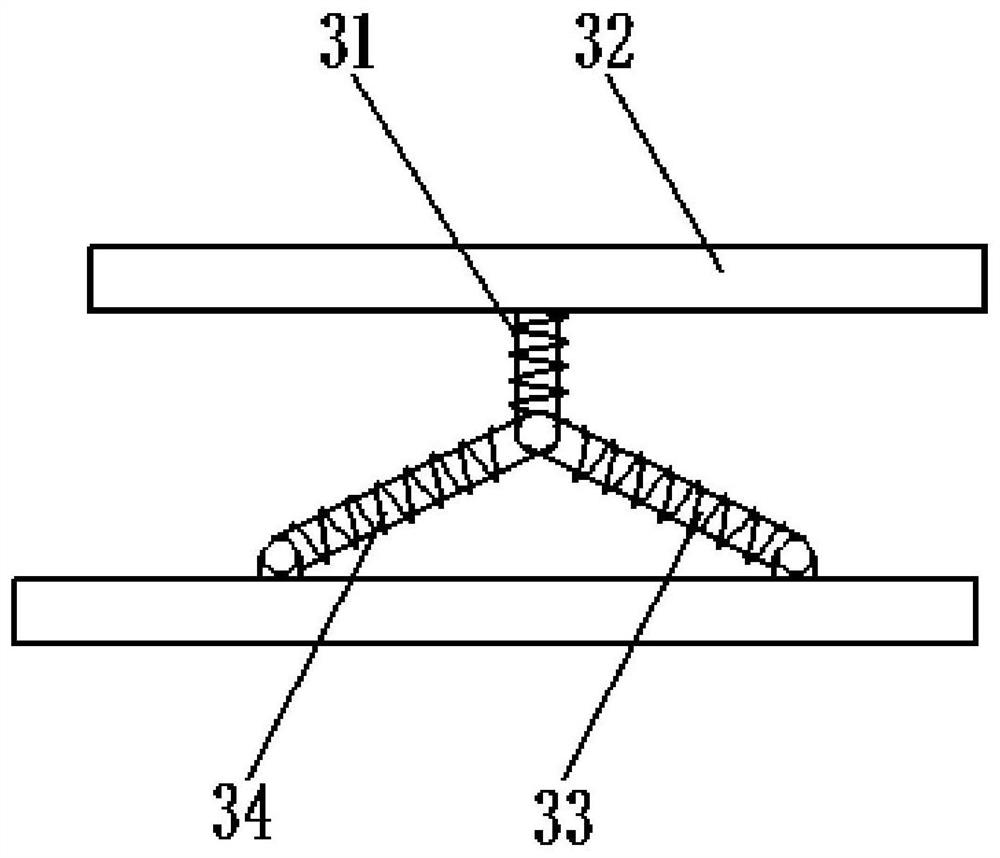
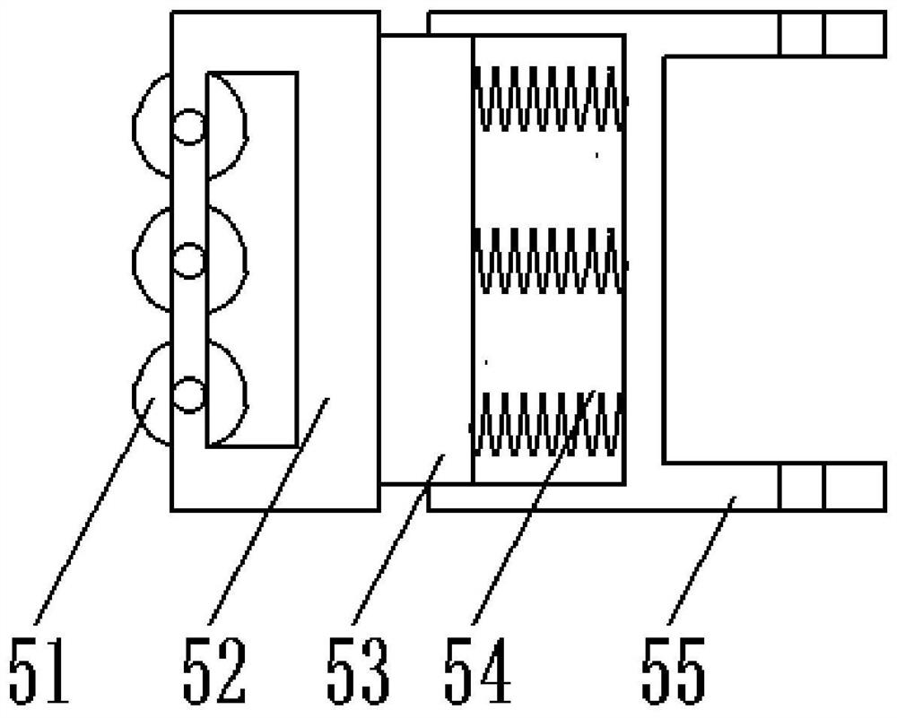
The invention discloses a fixing device for power equipment transportation. The fixing device for power equipment transportation comprises a moving wheel, a supporting plate and a bottom plate; the moving plate is arranged at the bottom of the bottom plate; damping elastic sheets and a damping device are arranged at the top of the bottom plate; the damping elastic sheets are arranged at the two ends of the bottom plate; one end of each damping elastic sheet is connected with the supporting plate and the other end of each damping elastic sheet is connected with the bottom plate; a sliding rod,a reset spring, a sleeve and a hydraulic lifter are arranged in the supporting plate; and buffer devices are arranged on the two sides of the supporting plate. Power equipment can be clamped for twice, so the fixing effect is greatly improved through mechanical preliminary clamping and positioning and manual fixation; furthermore, the device can be damped, so damage to the power equipment by too large vibration is avoided, an impact force generated by that the fixing device slides in the transportation process and collides with an object can be eliminated, and the safety of the power equipmentis guaranteed maximally.

Description

technical field [0001] The invention belongs to the technical field of electric equipment, and in particular relates to a fixing device for electric equipment transportation. Background technique [0002] Power equipment mainly includes power generation equipment and power supply equipment. Power generation equipment is mainly power plant boilers, steam turbines, gas turbines, water turbines, generators and transformers, etc. Power supply equipment is mainly transmission lines of various voltage levels, transformers, contactors, etc. The power components inside the power equipment are very easy to be damaged during the transportation process due to the shaking of the equipment or collision with the transportation place, resulting in the failure of the normal use of the power equipment, so it is often used during the transportation of power equipment to the fixing device, but the existing fixing device is often relatively simple in structure, and it is difficult to effectivel...

Claims


Application Information

Patent Timeline
Patent Type & Authority Patents(China)
IPC IPC(8): B62B3/02B62B3/04B62B5/00
CPCB62B3/02B62B3/04B62B5/00B62B5/0006B62B2202/00
Inventor 房玉杰高加海靳卫国李军强李民刘勇房朝阳张盼刘宁曹金星张建敏张迎亮张晶李军葛化庆邵伟芹冯富军周勇程昊燃
Owner JINAN CITY CHANGQING DISTRICT POWER SUPPLY CO OF STATE GRID SHANDONG ELECTRIC POWER CO
Learn More